Audi A6 Typ 4G: Bearing Bushing and Guide Pin, Replacing
Bearing Bushing and Guide Pin, Replacing, Steel Brakes 1LA/1LJ
Special tools and workshop equipment required
- Lithium grease. Refer to the Parts Catalog.
Removing
- Remove the brake pads. Refer to → Chapter "Brake Pads, Removing and Installing, Steel Brakes, 1LA/1LJ".
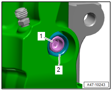
- Remove the bearing bushing -2- on the outside from the groove on the guide pin -1-.
- Pull the guide pin outward from the bearing bushing.
- Pull the bearing bushing out of the brake caliper.
Installing
- Thinly coat the guide pin with grease from the repair kit.
- Carefully press the guide pin into the bearing bushing as far as the first groove.
- Insert the bearing bushing into the brake caliper.
- The bearing bushing must be seated in the center of the brake caliper.
- Push the guide pin through the bearing bushing.
- The bearing bushing must not be seated in both grooves on the guide pin.
- Check the movement of both guide pins.
- Both guide pins must be able to slide.
- Install the brake pads. Refer to → Chapter "Brake Pads, Removing and Installing, Steel Brakes, 1LA/1LJ".
Bearing Bushing and Guide Pin, Replacing, Steel Brakes 1LF/1LL
Special tools and workshop equipment required
- Lithium grease. Refer to the Parts Catalog.
Removing
- Remove the brake pads. Refer to → Chapter "Brake Pads, Removing and Installing, Steel Brakes, 1LF/1LL".
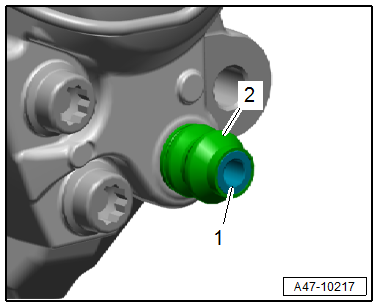
- Pull the guide pin -1- outward from the bearing bushing.
- Pull the bearing bushing -2- out of the brake caliper.
- Insert the bearing bushing into the brake caliper.
- The bearing bushing must be seated in the center of the brake caliper.
- Thinly coat the guide pin with grease from the repair kit.
- Push the guide pin into the bearing bushing.
- Check the movement of both guide pins.
- Both guide pins must be able to slide.
- Install the brake pads. Refer to → Chapter "Brake Pads, Removing and Installing, Steel Brakes, 1LF/1LL".