Audi A6 Typ 4G: Overview - Front Bumper Cover
Overview - Bumper Cover, Audi A6/S6 through MY 2014
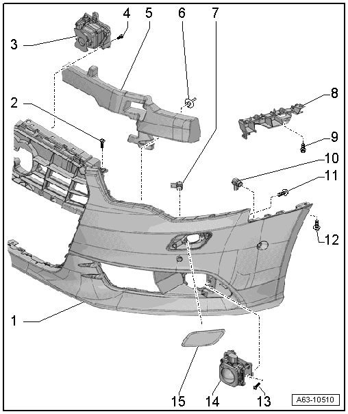
1 - Bumper Cover
- Removing and installing. Refer to → Chapter "Bumper Cover, Removing and Installing".
2 - Bolt
- 4 Nm
- Quantity: 2
3 - Mount
- For the Night Vision System Camera -R212-
- Removing and installing. Refer to → Chapter "Night Vision System Camera -R212- Mount, Removing and Installing, Vehicles through MY 2014".
4 - Bolt
- 6 Nm
- Quantity: 4
5 - Molded Foam Piece
- Removing and installing. Refer to → Chapter "Molded Foam Part, Removing and Installing, Audi A6/S6 through MY 2014".
6 - Clip
- Quantity: 2
7 - Front Parking Aid Sensor
- Removing and installing. Refer to → Electrical Equipment; Rep. Gr.94; Parking Aid; Front Parking Aid Sensor, Removing and Installing.
8 - Front Bumper Cover Mount
- Removing and installing. Refer to → Chapter "Front Bumper Cover Mount, Removing and Installing".
9 - Bolt
- 4 Nm
- Quantity: 2
10 - Parallel Parking Assistance Front Sensor
- Removing and installing. Refer to → Electrical Equipment; Rep. Gr.94; Parallel Parking Assist; Front Sensor, Removing and Installing.
11 - Bolt
- 4 Nm
12 - Bolt
- 1.5 Nm
13 - Bolt
- Tightening specification. Refer to → Electrical Equipment; Rep. Gr.27; Adaptive Cruise Control; Overview - Adaptive Cruise Control (ACC).
14 - Distance Regulation Control Module (ACC)
- Removing and installing. Refer to → Electrical Equipment; Rep. Gr.27; Adaptive Cruise Control; Control Module for Adaptive Cruise Control, Removing and Installing.
15 - Spray Nozzle Cover
- For the headlamp washer system
- Removing and installing. Refer to → Chapter "Headlamp Washer System Spray Nozzle Cover, Removing and Installing".
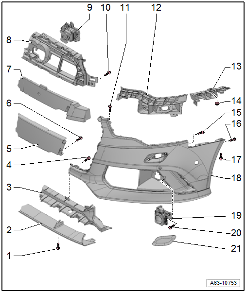
Overview - Bumper Cover, Audi A6 from MY 2015
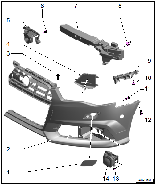
1 - Spray Nozzle Cover
- For the headlamp washer system
- Removing and installing. Refer to → Chapter "Headlamp Washer System Spray Nozzle Cover, Removing and Installing".
2 - Bumper Cover
- Removing and installing. Refer to → Chapter "Bumper Cover, Removing and Installing".
3 - Bolt
- 4 Nm
- Quantity: 2
4 - Cover
- For the air intake grille
- Equipment levels
5 - Mount
- For the Night Vision System Camera -R212-
- Removing and installing. Refer to → Chapter "Night Vision System Camera -R212- Mount, Removing and Installing, Vehicles from MY 2015".
6 - Bolt
- 6 Nm
- Quantity: 4
7 - Molded Foam Piece
- Removing and installing. Refer to → Chapter "Molded Foam Part, Removing and Installing, Audi A6 from MY 2015".
8 - Clip
- Quantity: 2
9 - Front Bumper Cover Mount
- Removing and installing. Refer to → Chapter "Front Bumper Cover Mount, Removing and Installing".
10 - Bolt
- 4 Nm
- Quantity: 2
11 - Bolt
- 4 Nm
12 - Bolt
- 1.5 Nm
13 - Bolt
- Tightening specification. Refer to → Electrical Equipment; Rep. Gr.27; Adaptive Cruise Control; Overview - Adaptive Cruise Control (ACC).
14 - Distance Regulation Control Module (ACC)
- Removing and installing. Refer to → Electrical Equipment; Rep. Gr.27; Adaptive Cruise Control; Control Module for Adaptive Cruise Control, Removing and Installing.
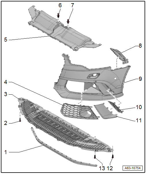
Overview - Bumper Cover, Lock Carrier Cover End Panel, Audi A6/S6
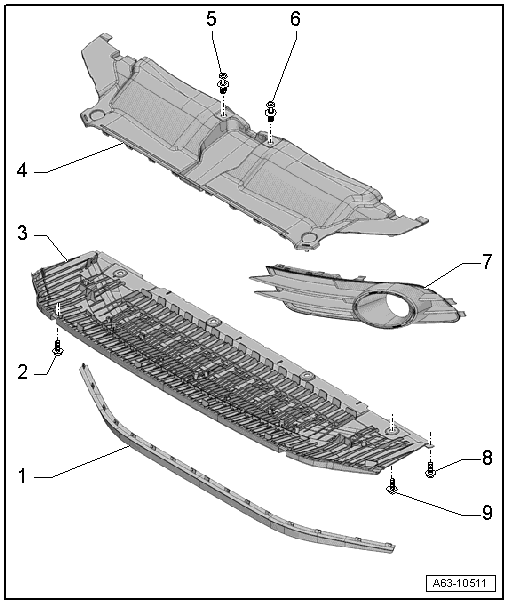
1 - Spoiler Lip
- Removing and installing. Refer to → Chapter "Spoiler Lip, Removing and Installing".
2 - Bolt
- 1.5 Nm
- Quantity: 5
3 - Bumper Cover End Plate
- Removing and installing. Refer to → Chapter "Front Bumper Cover End Plate, Removing and Installing, Audi A6/S6".
4 - Lock Carrier Cover
- Removing and installing. Refer to → Chapter "Lock Carrier Cover, Removing and Installing".
5 - Expanding Clip
6 - Expanding Clip
7 - Air Intake Grille
- Removing and installing. Refer to → Chapter "Air Intake Grille, Removing and Installing".
8 - Bolt
- 2.1 Nm
- Quantity: 2
9 - Bolt
- 5 Nm
- Quantity: 4
Overview - Bumper Cover, Allroad
 Note
Note
- Only the differences from the standard bumper are described.
- The removal and installation of the bumper cover is performed like that of the standard bumper.
1 - Impact Protection
- The end plate -2- is removed.
- Remove the screws -16- and -18-.
- Unclip the clips on the inside one after the other and then pull off the impact protection.
2 - End Plate
- Turn the left-hand quick-release fasteners -17- to loosen them and then remove the screws -16- and -18-.
- Remove the end plate to the rear.
3 - Bolt
- 1.5 Nm
4 - Connecting Piece
- Clipped into the bumper cover between the left and right spoilers.
5 - Bolt
- 2 Nm
6 - Right Spoiler
- Can be replaced separately
- Bumper cover removed.
- Unclip the spoiler one clip after the other and then pull it off the bumper cover.
7 - Right Air Intake Grille
- The end plate -2- is removed.
- Unclip in steps from the inside and pull it off.
8 - Bumper Cover
- Removing. Refer to → Chapter "Bumper Cover, Removing and Installing".
9 - Radiator Grille
- Removing and installing. Refer to → Chapter "Radiator Grille, Removing and Installing, Audi A6/allroad/S6 through MY 2014".
10 - Bolt
- 1.5 Nm
11 - Center Air Intake Grille
- Remove the end plate.
- Remove the screws -10- and remove the air intake grille.
12 - Bolt
- 1.5 Nm
13 - Left Air Intake Grille
- The end plate -2- is removed.
- Unclip in steps from the inside and pull it off.
14 - Bolt
- 2 Nm
15 - Left Spoiler
- Can be replaced separately
- Bumper cover removed.
- Unclip the spoiler one clip after the other and then pull it off the bumper cover.
16 - Bolt
- 1.5 Nm
17 - Quick Release
- Open by turning counter-clockwise
- Quantity: 4
18 - Bolt
- 1.5 Nm
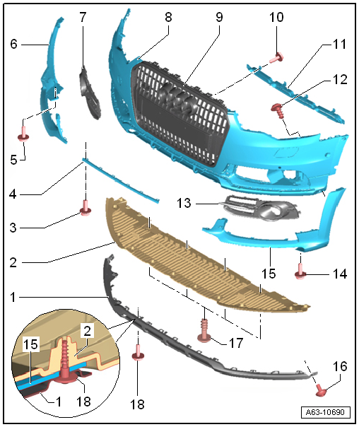
Overview - Bumper Cover, Audi RS 6
1 - Bolt
- 2 Nm
- Quantity: 2
2 - Spoiler Lower Section
- Removing and installing. Refer to → Chapter "Spoiler Lower Section, Removing and Installing".
3 - Mount
- For the spoiler lower part
- Removing and installing. Refer to → Chapter "Spoiler Lower Section Mount, Removing and Installing".
4 - Bolt
- Quantity: 4
- 2 Nm
5 - Mount
- For the molded foam part
- Removing and installing. Refer to → Chapter "Molded Foam Part Mount, Removing and Installing, Audi RS 6".
6 - Bolt
- Quantity: 2
- 1.5 Nm
7 - Molded Foam Piece
- Removing and installing. Refer to → Chapter "Molded Foam Part, Removing and Installing, Audi RS 6".
8 - Center Reinforcement Brace
- Removing and installing. Refer to → Chapter "Center Reinforcement Brace, Removing and Installing, Vehicles through MY 2014".
9 - Mount
- For the Night Vision System Camera -R212-
- Removing and installing. Refer to → Chapter "Night Vision System Camera -R212- Mount, Removing and Installing, Vehicles through MY 2014".
10 - Bolt
- 1.5 Nm
- Quantity: 14
11 - Bolt
- 3 Nm
- Quantity: 2
12 - Side Reinforcement Brace
- Removing and installing. Refer to → Chapter "Side Reinforcement Brace, Removing and Installing, Vehicles through MY 2014".
13 - Front Bumper Cover Mount
- Removing and installing. Refer to → Chapter "Front Bumper Cover Mount, Removing and Installing".
14 - Nut
- 4 Nm
- Quantity: 3
15 - Bolt
- 4 Nm
16 - Bolt
- 1.5 Nm
17 - Bolt
- 1.5 Nm
18 - Bumper Cover
- Removing and installing. Refer to → Chapter "Bumper Cover, Removing and Installing".
19 - Distance Regulation Control Module (ACC)
- Removing and installing. Refer to → Electrical Equipment; Rep. Gr.27; Adaptive Cruise Control; Control Module for Adaptive Cruise Control, Removing and Installing.
20 - Bolt
- Tightening specification. Refer to → Electrical Equipment; Rep. Gr.27; Adaptive Cruise Control; Overview - Adaptive Cruise Control (ACC).
21 - Spray Nozzle Cover
- For the headlamp washer system
- Removing and installing. Refer to → Chapter "Headlamp Washer System Spray Nozzle Cover, Removing and Installing".
Overview - Bumper Cover, Lock Carrier Cover End Panel, Audi RS 6
1 - Spoiler Lip
- Removing and installing. Refer to → Chapter "Spoiler Lip, Removing and Installing".
2 - Bolt
- 1.5 Nm
- Quantity: 7
3 - Bumper Cover End Plate
- Removing and installing. Refer to → Chapter "Front Bumper Cover End Plate, Removing and Installing, Audi RS 6".
4 - Inner Air Intake Grille
- There are different versions. Refer to the Parts Catalog.
- Removing and installing. Refer to → Chapter "Inner Air Intake Grille, Removing and Installing, Audi RS 6".
5 - Lock Carrier Cover
- Removing and installing. Refer to → Chapter "Lock Carrier Cover, Removing and Installing".
6 - Expanding Clip
7 - Expanding Clip
8 - Mount
- For the exterior air intake grille
9 - Bumper Cover
10 - Exterior Air Intake Grille
- Removing and installing. Refer to → Chapter "Outer Air Intake Grille, Removing and Installing, Audi RS 6".
11 - Trim
- For the exterior air intake grille
- Removing and installing. Refer to → Chapter "Outer Air Intake Grille, Removing and Installing, Audi RS 6".
12 - Bolt
- 2.1 Nm
- Quantity: 2
13 - Bolt
- 5 Nm
- Quantity: 4
Overview - Impact Member
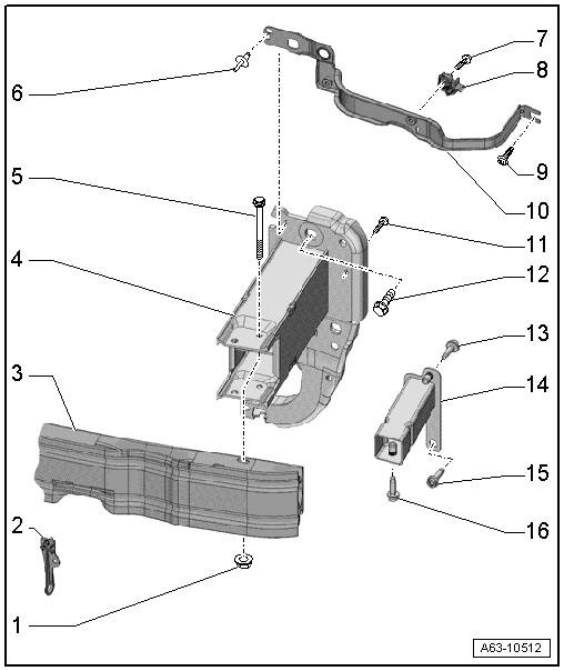
1 - Nut
- Quantity: 2
- Tightening specification. Refer to → Fig. "Front Impact Member - Tightening Specification and Sequence".
2 - Bracket
- For Outside Air Temperature Sensor -G17-
- Removing and installing. Refer to → Chapter "Outside Air Temperature Sensor -G17- Bracket, Removing and Installing".
3 - Impact Member
- Removing and installing: For the left side. Refer to → Chapter "Left Impact Member Mount, Removing and Installing". For the right side. Refer to → Chapter "Right Impact Member Mount, Removing and Installing".
4 - Impact Member Mount
- Removing and installing. Refer to → Chapter "Left Impact Member Mount, Removing and Installing".
5 - Bolt
- Quantity: 2
6 - Rivet
- Secures the lock carrier
7 - Bolt
- Tightening specification. Refer to → Body Interior; Rep. Gr.69; Airbag Crash Sensors; Component Location Overview - Airbag Crash Sensors.
8 - Front Airbag Crash Sensor
- Removing and installing. Refer to → Body Interior; Rep. Gr.69; Airbag Crash Sensors; Component Location Overview - Airbag Crash Sensors.
9 - Bolt
- 4.5 Nm
10 - Connecting Brace
- For supporting the front bumper cover mount
- Removing and installing. Refer to → Chapter "Connecting Brace, Removing and Installing".
11 - Bolt
- 18 Nm
- Quantity: 4
12 - Bolt
- 55 Nm
- Quantity: 3
13 - Bolt
- 20 Nm
14 - Lower Front Longitudinal Member
- Removing and installing. Refer to → Chapter "Lower Front Longitudinal Member, Removing and Installing".
15 - Bolt
- 20 Nm
16 - Bolt
- 20 Nm
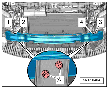
Front Impact Member - Tightening Specification and Sequence
- Tighten the nuts -A- to 20 Nm in the following sequence: -1 through 4-.