Audi A6 Typ 4G: Rear Brake Pad Wear Indicator Wire, Removing and Installing
Brake Pad Wear Indicator Wire, Removing and Installing, Steel Brakes
 Note
Note
The brake pad wear sensor contacts cannot be removed without damaging them.
Removing
- Remove the affected rear wheel. Refer to → Suspension, Wheels, Steering; Rep. Gr.44; Wheels, Tires.
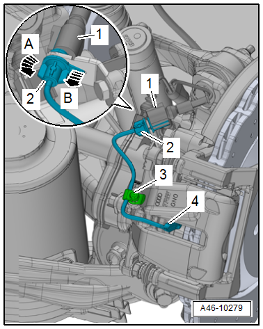
- Disconnect the brake pad wear sensor connector -1-.
- Release the connector -2- to the brake pad wear sensor from its bracket -arrow B- while turning it 90º at the same time -arrow A-.
- Remove the dust cap -3- from the bleed screw and free up the electrical wire.
- Remove the brake pad wear sensor contact -4- with pliers.
Installing
- Insert the new contact -1- for the brake pad wear sensor into the inner brake pad until it engages.
Note
Make sure that the brake pad wear sensor contact sits correctly in the brake pad.
- Secure the electrical wire for the brake pad wear sensor with the dust cap -2- as illustrated.
- Bring the connector -3- into its installed position and turn in the direction of the -arrow- until the tab -4- engages in the hole -5- on the bracket.
- Assemble connector -6-.
- Install the rear wheel. Refer to → Suspension, Wheels, Steering; Rep. Gr.44; Wheels, Tires.

Brake Pad Wear Indicator Wire, Removing and Installing, Ceramic Brakes
Note
The brake pad wear sensor contacts cannot be removed without damaging them.
Removing
- Remove the affected rear wheel, while observing the safety precautions for vehicles with ceramic brakes. Refer to → Suspension, Wheels and Steering; Rep. Gr.44; Wheels, Tires.
- Unclip the bracket -3- with a screwdriver -2--arrow-.
- Free up the brake pad wear indicator wire -1-.

- Disconnect the brake pad wear sensor connector -1-.
- Release the connector -2- to the brake pad wear sensor from its bracket -arrow B- while turning it 90º at the same time -arrow A-.
- Remove the dust cap -3- from the bleed screw and free up the electrical wire.
- Remove the brake pad wear sensor contacts -4- with pliers.

Installing
- Insert the brake pad wear sensor contacts -5- into the brake pads until they engage.
Note
Make sure that the brake pad wear sensor contacts fit correctly in the brake pads.
- Secure the electrical wire for the brake pad wear sensor with the dust cap -4- as illustrated.
- Bring the connector into its installed position and turn in the direction of the -arrow- until the tab -1- engages in the hole -2- on the bracket.
- Connect the connector -3-.
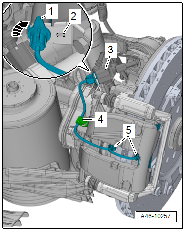
- Guide the electrical wire -1- for the brake pad wear sensor into the bracket -3- as illustrated.
- Clip the bracket into the brake caliper.
Note
Ignore -item 2- and -arrow-.
- Install the rear wheel, while observing the safety precautions for vehicles with ceramic brakes. Refer to → Suspension, Wheels and Steering; Rep. Gr.44; Wheels, Tires.

