Audi A6 Typ 4G: Steering Wheel
Overview - Steering Wheel
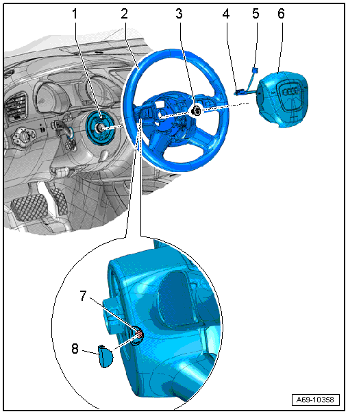
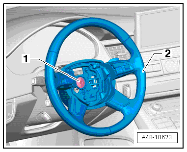
1 - Steering Column Electronics Control Module -J527-
- Removing and installing. Refer to → Electrical Equipment; Rep. Gr.94; Steering Column Switch Module; Steering Column Electronics Control Module J527, Removing and Installing.
2 - Airbag Steering Wheel
- Removing and installing. Refer to → Chapter "Steering Wheel, Removing and Installing".
3 - Bolt
- 50 Nm
- Always replace if removed
4 - Connector
5 - Connector
6 - Driver Side Airbag
- Removing and Installing. Refer to → Body Interior; Rep. Gr.69; Driver Side Airbag; Airbag Unit with Igniter, Removing and Installing.
 WARNING
Follow the safety precautions when working on airbags. Refer to → Body Interior; Rep. Gr.00; Safety Precautions; Pyrotechnic Components Safety Precautions.
7 - Locking Bracket
- Releasing. Refer to → Body Interior; Rep. Gr.69; Driver Side Airbag; Airbag Unit with Igniter, Removing and Installing.
8 - Cap
- Not installed on this model
Steering Wheel, Removing and Installing
Special tools and workshop equipment required
- Torque Wrench 1331 5-50Nm -VAG1331-
- Steering Wheel Scales -VAS6458-
Removing
 Note
Note
- Applies to vehicles equipped with dynamic steering:
- Before the steering wheel can be removed from the steering column, the steering wheel must be in the exact horizontal using the Steering Wheel Scales -VAS6458-. Mount the new steering wheel so that it is horizontal using the Steering Wheel Level -VAS6458-.
- After doing this step, the Steering Angle Sensor -G85- for setting the steering wheel position must be checked. While doing this, select the appropriate measured values block in the Steering Column Electronics Control Module -J527- in on board diagnostics. If the displayed value is > 0.5º, then the Steering Angle Sensor -G85- must be calibrated again and the dynamic steering must be adapted, by starting the correct program using the Vehicle Diagnostic Tester in Guided Functions.
- Straighten the wheels.
- Position steering wheel as far back as possible. Use entire steering column adjustment range to do this.
- Remove the driver side airbag. Refer to → Body Interior; Rep. Gr.69; Driver Side Airbag; Airbag Unit with Igniter, Removing and Installing.
Note
Removal and installation of steering wheel must take place in center position (wheels in straight-ahead position).
- Remove the bolt -1-.
- Mark position of steering wheel/column with a felt-tip pen.
- Remove steering wheel -2- from steering column.
Installing
Install in reverse order of removal. Note the following:
Before positioning steering wheel, make sure wheels are in straight position.
- When installing removed steering wheel: Make sure that markings on steering column/wheel align.
- When installing a new steering wheel (without marking): Steering wheel must be position in center position (steering wheel spoke must be horizontal and wheels in straight-ahead position).
- Install steering wheel.
- Install the airbag unit. Refer to → Body Interior; Rep. Gr.69; Driver Side Airbag; Airbag Unit with Igniter, Removing and Installing.
- Perform road test.
- If steering wheel is crooked, remove it again and rotate it on steering column splines.