Audi A6 Typ 4G: Subframe, Securing
Subframe, Securing, FWD
Certain repairs on a vehicle require the removal of the subframe or the complete rear axle. The original position of the subframe to the body can be maintained with assistance of the Subframe Locating Pins -T40242-. The Subframe Locating Pins -T40242- must always be installed just before lowering the subframe or the complete rear axle. A road test must be performed after completing repairs. If when driving in a straight line on a level road surface the steering wheel must be turned off the center position to compensate for pulling, the vehicle must be aligned. Refer to → Chapter "Vehicle Alignment".
Special tools and workshop equipment required
- Torque Wrench 1331 5-50Nm -VAG1331-
- Torque Wrench 1332 40-200Nm -VAG1332-
- Engine and Gearbox Jack -VAS6931-
- Subframe Locating Pins -T40242-
Procedure
- Remove the rear section from the exhaust system. Refer to → Rep. Gr.26; Exhaust Pipes/Mufflers; Overview - Muffler.
- Place the Engine and Gearbox Jack -VAS6931- under the subframe.
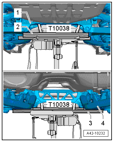
- Support the back of the subframe -1- with a piece of wood -2-.
- Support the front of the subframe -4- with a piece of wood -3-.
- Secure the subframe to the Engine and Gearbox Jack -VAS6931- using the Tensioning Strap -T10038- as illustrated.
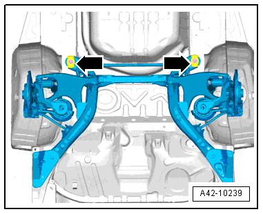
- Remove the bolts -arrows-.
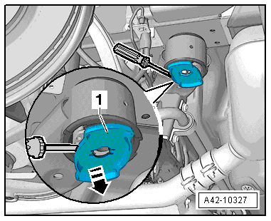
- Pry the stop plate -1- off the bonded rubber bushing alternating from side to side.
- Tighten the Subframe Locating Pins -T40242- to 20 Nm.
- The subframe position is now secured.
The removal of the Subframe Locating Pins -T40242- is performed in reverse order.
Subframe, Securing, Vehicles with AWD
Certain repairs on a vehicle require the removal of the subframe or the complete rear axle. The original position of the subframe to the body can be maintained with assistance of the Subframe Locating Pins -T40242-. The Subframe Locating Pins -T40242- must always be installed just before lowering the subframe or the complete rear axle. A road test must be performed after completing repairs. If steering wheel is crooked, vehicle must be aligned → Chapter "Vehicle Alignment".
Special tools and workshop equipment required
- Torque Wrench 1331 5-50Nm -VAG1331-
- Torque Wrench 1332 40-200Nm -VAG1332-
- Engine and Gearbox Jack -VAS6931-
- Subframe Locating Pins -T40242-
Procedure
- Place the Engine and Gearbox Jack -VAS6931- under the subframe.
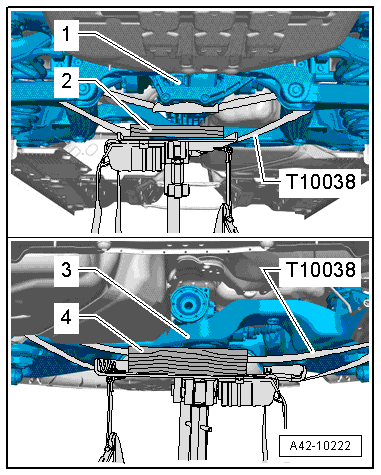
- Support the rear final drive -1- using a suitable wood block -2-.
- Support front of subframe with a suitable wood block -4- under crossmember -3-.
- Secure the subframe to the Engine and Gearbox Jack -VAS6931- using the Tensioning Strap -T10038-.
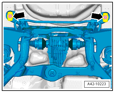
- Secure the Tensioning Strap -T10038- under the drive axle and around the subframe and guide it behind the rear final drive and tighten it as illustrated.
- Remove the bolts -arrows-.
- Pry the stop plate -1- off the bonded rubber bushing alternating from side to side.
- Tighten the Subframe Locating Pins -T40242- to 20 Nm.
- The subframe position is now secured.
The removal of the Subframe Locating Pins -T40242- is performed in reverse order.

