Audi A6 Typ 4G: Commercially Available Tools and Materials
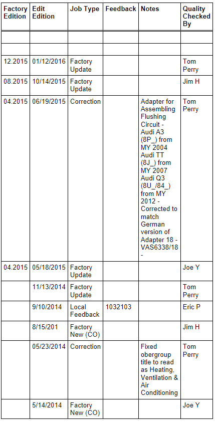
Fin comb
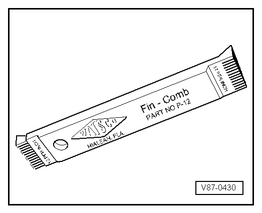
Fill hoses
5/8"-18 UNF thread
 Note
Note
- Use differently colored charging hoses (1800 mm long).
- Have valve opener and spare seals to hand.
- A charging hose in short version is also included in Refrigerant Circuits Adapter Set 1 -VAS6338/1-.
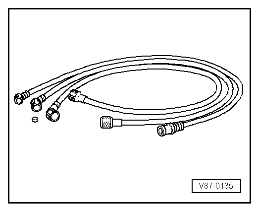
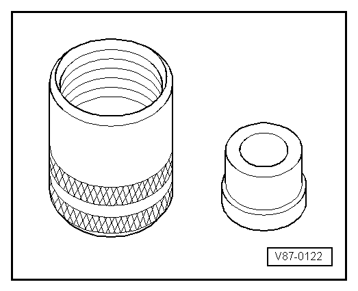
Connection piece for refrigerant cylinder with seal, quick-release coupling connection or threaded connection 5/8" - 18 UNF
Valve caps with spare seals (for 5/8"-18 UNF thread)
Seals can also be used for charging hoses.
Note
Valve caps with spare seals are also included in Refrigerant Circuits Adapter Set 1 -VAS6338/1-.
Pressure gauge set with pressure reducer for nitrogen (max. reducing pressure: 15 bar (218 psi) )
1 - Pressure gauge set
2 - Pressure hose (inner diameter 5 mm, length 2 m)
3 - Nitrogen
4 - Hose fitting
Note
For connection to A/C Adapter Set -VAG1785- with 5/8"-18 UNF thread.

Quick-release coupling adapter for service connections
- High-pressure side, nominal size 16 mm
- Low-pressure side, nominal size 13 mm
- 2x release tool (Sharan)
Note
This quick-release coupling is delivered with the service station.

Improvised Tools
Charging hose with connection for workshop compressed-air system
A - Charging hose 5/8" - 18 UNF** (version with large inner diameter)
B - Connection for workshop compressed-air system ** (always use filter)

Revision History
DRUCK NUMBER: A0053300221