Audi A6 Typ 4G: Component Location Overview - Windshield Wiper System
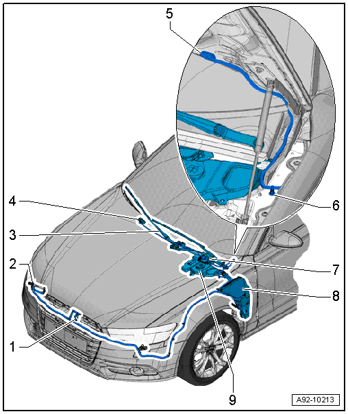
1 - Spray Nozzle for Night Vision System Camera -R212-
- Overview. Refer to → Chapter "Overview - Headlamp Washer System".
2 - Headlamp Washer System Spray Nozzle
- Overview. Refer to → Chapter "Overview - Headlamp Washer System".
3 - Wiper Arm
- Overview. Refer to → Chapter "Overview - Windshield Wiper System".
4 - Spray Nozzle
- Overview. Refer to → Chapter "Overview - Windshield Washer System".
5 - Grommet
- For the windshield washer fluid hose inside the hood
6 - Grommet
- For the windshield washer fluid hose on the fender
7 - Windshield Wiper Motor -V-
- With Wiper Motor Control Module -J400-
- Overview. Refer to → Chapter "Overview - Windshield Wiper System".
8 - Windshield Washer Fluid Reservoir
- Overview. Refer to → Chapter "Overview - Windshield Washer System".
9 - Filler Tube
- For the windshield washer fluid reservoir
- Overview. Refer to → Chapter "Overview - Windshield Washer System".
Overview - Windshield Wiper System
Overview - Windshield Wiper System
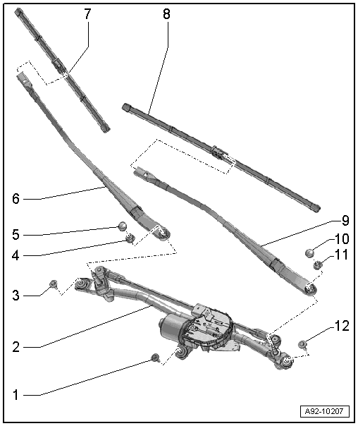
1 - Screw
- Tightening sequence. Refer to → Fig. "Tightening Specifications and Sequence for the Windshield Wiper Motor".
2 - Windshield Wiper Motor -V-
- With Wiper Motor Control Module -J400-
- Removing and installing. Refer to → Chapter "Windshield Wiper Motor -V-, Removing and Installing".
- Replacing. Refer to → Chapter "Windshield Wiper Motor, Replacing".
3 - Screw
- Tightening sequence. Refer to → Fig. "Tightening Specifications and Sequence for the Windshield Wiper Motor".
4 - Nut
- 22 Nm
5 - Cap
6 - Passenger Side Windshield Wiper Arm
- There are different lengths. Refer to the Parts Catalog.
- Removing and installing. Refer to → Chapter "Windshield Wiper Arms, Removing and Installing".
- Adjusting. Refer to → Chapter "Windshield Wiper Arms, Adjusting".
7 - Passenger Side Windshield Wiper Blade
- There are different lengths. Refer to the Parts Catalog.
- Replacing. Refer to → Chapter "Wiper Blade, Removing and Installing".
8 - Driver Side Windshield Wiper Blade
- There are different lengths. Refer to the Parts Catalog.
- Replacing. Refer to → Chapter "Wiper Blade, Removing and Installing".
9 - Driver Side Windshield Wiper Arm
- There are different lengths. Refer to the Parts Catalog.
- Removing and installing. Refer to → Chapter "Windshield Wiper Arms, Removing and Installing".
- Adjusting. Refer to → Chapter "Windshield Wiper Arms, Adjusting".
10 - Cap
11 - Nut
- 22 Nm
12 - Screw
- Tightening sequence. Refer to → Fig. "Tightening Specifications and Sequence for the Windshield Wiper Motor".
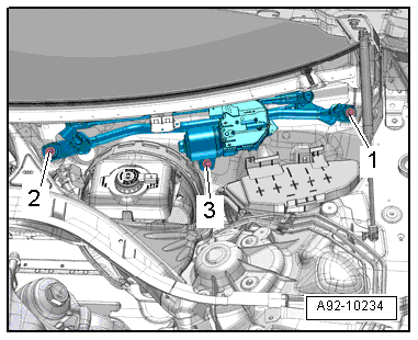
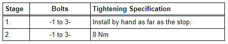
Tightening Specifications and Sequence for the Windshield Wiper Motor
- Tighten the bolts in stages in the sequence shown:
Overview - Windshield Wiper System, Rain/Light Recognition Sensor
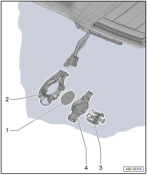
1 - Silicon Pad
- There are different versions. Refer to the Parts Catalog.
- Replace after removal
2 - Retaining Plate
- For Rain/Light Recognition Sensor -G397-
- Attached to the windshield
3 - Clamp
4 - Rain/Light Recognition Sensor -G397-
- There are different versions. Refer to the Parts Catalog.
- Removing and installing. Refer to → Chapter "Rain/Light Recognition Sensor -G397-, Removing and Installing, with Humidity Sensor -G355-".
- Replacing. Refer to → Chapter "Rain/Light Recognition Sensor -G397-, Replacing, with Humidity Sensor -G355-".

