Audi A6 Typ 4G: Drive Axle, Removing and Installing
Removing
- Loosen the connection between the drive axle and wheel hub. Refer to → Chapter "Drive Axle Threaded Connection, Loosening and Tightening".
- Remove the rear wheel. Refer to → Chapter "Wheels and Tires".
Vehicles with Steel Suspension
- Remove the coil spring. Refer to → Chapter "Spring, Removing and Installing, Coil Spring".
Vehicles with Air Suspension
- Bleed the rear axle air spring. Refer to → Chapter "System, Venting or Filling".
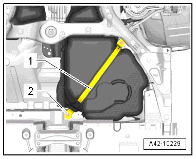
- Tighten the bolt -2- just hand-tight and secure the mounting strap -1-.
- Remove the rear final drive. Refer to → Rear Final Drive; Rep. Gr.39.
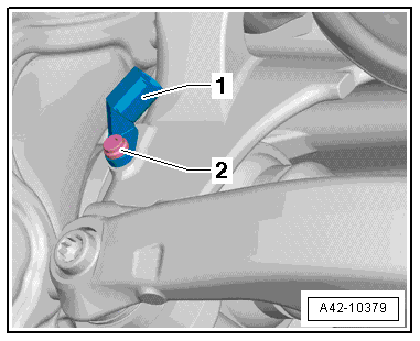
- Remove the bolt -2- and the rear speed sensor -1-.
- Remove the drive axle toward the inside.
Installing
Install in reverse order of removal. Note the following:
- Install the rear final drive. Refer to → Rear Final Drive 0BC, 0BD, 0BE, 0BF; Rep. Gr.39.
- Install the speed sensor. Refer to → Brake System; Rep. Gr.45.
- Install rear wheel. Refer to → Chapter "Wheels and Tires".
- Fill the rear axle air springs. Refer to → Chapter "System, Venting or Filling".
- Tighten the drive axle to wheel hub threaded connection. Refer to → Chapter "Drive Axle Threaded Connection, Loosening and Tightening".
Drive Axle Threaded Connection, Loosening and Tightening
Special tools and workshop equipment required
- Torque Wrench 80-400Nm -VAG1576-
Loosen the threaded connection between the drive axle and wheel hub
- With vehicle still standing on its wheels, loosen bolt a maximum of 90º, otherwise wheel bearing will be pre-damaged.
- Remove the rear wheel. Refer to → Chapter "Wheels and Tires".
- Lift the vehicle just enough so that the wheels are hanging free.
- Have a second technician push the brake pedal.
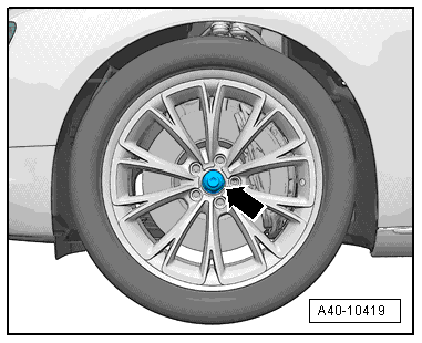
- Remove the bolt -arrow-.
Tighten the threaded connection between the drive axle and wheel hub
- Replace bolt -arrow-.
 Note
Note
- Before installing, clean the threads in the CV joint with a tap.
- Wheels must not yet touch the ground to tighten the drive axle, wheel bearing may otherwise be damaged.
- Have a second technician push the brake pedal.
- Tighten bolt to 200 Nm.
- Lower the vehicle onto its wheels.
- Tighten bolt an additional 180º turn.

