Audi A6 Typ 4G: Front Brake Rotor, Replacing
Removing
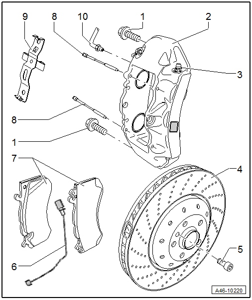
- Remove the brake caliper -2-.
- Remove the locking pin-5- on the brake rotor -4- while holding the brake rotor firmly.
- Remove the brake rotor from the wheel hub.
 Note
Note
When removing the brake rotor from the wheel hub, do not tilt the brake rotor.
Installing
- Tightening Specifications
Note
- Only install brake rotors from the same manufacturer and with the same quality level on a single axle.
- Always replace brake rotors on both sides of the axle.
- Use new bolts.
- Clean the contact surface on the wheel hub. Remove any corrosion.
- Place the brake rotor on the hub.
Note
When positioning the brake rotor, do not tilt it on the wheel hub.
- Install the securing bolt -5- and tighten.
- Install the brake caliper -2-.
 WARNING
Risk of accident!
- With the vehicle stationary, firmly press the brake pedal several times so that the brake pads in the operating condition properly sit in their respective position.
- Make sure the brakes are working correctly before driving the vehicle for the first time.
Front Brake Shield, Removing and Installing
Special tools and workshop equipment required
- Torque Wrench 1331 5-50Nm -VAG1331-
Removing
- Remove the brake rotor. Refer to → Chapter "Brake Rotor, Removing and Installing".
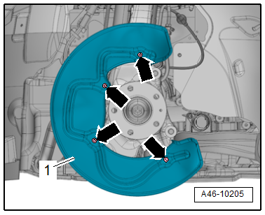
- Remove the bolts -arrows- and the cover plate -1-.
Note
The brake shield is shown on a vehicle with ceramic brakes.
Installing
Install in reverse order of removal and note the following:
- Clean the brake shield and the wheel hub.
- Install the brake rotor. Refer to → Chapter "Brake Rotor, Removing and Installing".
WARNING
Risk of accident!
- With the vehicle stationary, firmly press the brake pedal several times so that the brake pads in the operating condition properly sit in their respective position.
- Make sure the brakes are working correctly before driving the vehicle for the first time.