Audi A6 Typ 4G (2011–2018) Workshop Manual / Chassis / Suspension, Wheels, Steering / Front Suspension / Overview - Suspension Strut and Upper Control Arm
Audi A6 Typ 4G: Overview - Suspension Strut and Upper Control Arm
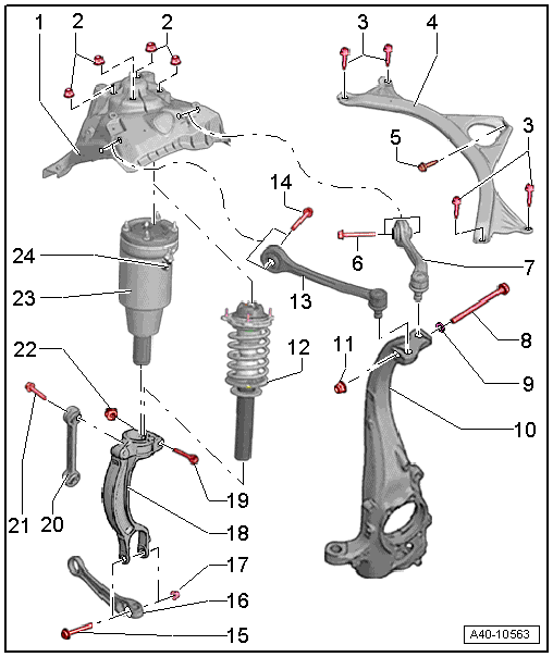
1 - Suspension Strut Dome
2 - Nut
- 30 Nm
- Loosen and tighten diagonally
- Always replace if removed
3 - Bolt
- 20 Nm
4 - Tower Brace
- Removing and installing. Refer to → Chapter "Tower Brace, Removing and Installing".
5 - Bolt
- 20 Nm
6 - Bolt
- 50 Nm +90º turn
- Always replace if removed
- Must be tightened in the control position. Refer to → Chapter "Wheel Bearing in Control Position, Lifting Vehicles with Air Suspension" or → Chapter "Wheel Bearing in Curb Weight, Lifting Vehicles with Coil Spring".
7 - Upper Rear Control Arm
- Removing and installing. Refer to → Chapter "Upper Control Arm, Removing and Installing".
- For replacing the bonded rubber bushing for upper rear control arm. Refer to → Chapter "Upper Control Arm Bearing, Replacing".
8 - Bolt
- Always replace if removed
9 - Washer
10 - Wheel Bearing Housing
11 - Nut
- 40 Nm
- Always replace if removed
12 - Coil Spring Shock Absorber
- Removing and installing. Refer to → Chapter "Suspension Strut, Removing and Installing, Coil Spring Shock Absorber".
- Servicing. Refer to → Chapter "Suspension Strut, Servicing, Coil Spring Shock Absorber".
13 - Upper Front Control Arm
- Removing and installing. Refer to → Chapter "Upper Control Arm, Removing and Installing".
- For replacing the bonded rubber bushing for upper front control arm. Refer to → Chapter "Upper Control Arm Bearing, Replacing".
14 - Bolt
- 50 Nm +90º turn
- Always replace if removed
- Must be tightened in the control position. Refer to → Chapter "Wheel Bearing in Control Position, Lifting Vehicles with Air Suspension" or → Chapter "Wheel Bearing in Curb Weight, Lifting Vehicles with Coil Spring".
15 - Bolt
- Always replace if removed
16 - Control Arm
17 - Nut
- 90 Nm +90º turn
- Always replace if removed
- Must be tightened in the control position. Refer to → Chapter "Wheel Bearing in Control Position, Lifting Vehicles with Air Suspension"
18 - Shock Absorber Fork
- Removing and installing. Refer to → Chapter "Shock Absorber Fork, Removing and Installing".
19 - Bolt
- 40 Nm +180º turn
- Always replace if removed
20 - Coupling Rod
21 - Bolt
- 40 Nm +90º turn
- Always replace if removed
- Must be tightened in the control position. Refer to → Chapter "Wheel Bearing in Control Position, Lifting Vehicles with Air Suspension" or → Chapter "Wheel Bearing in Curb Weight, Lifting Vehicles with Coil Spring".
22 - Nut
- Always replace if removed
23 - Air Spring Shock Absorber
- Removing and installing. Refer to → Chapter "Suspension Strut, Removing and Installing, Air Spring Damper".
- Servicing. Refer to → Chapter "Suspension Strut, Servicing, Air Spring Damper".
- There are different versions of the suspension. Refer to → Chapter "Production Control Number (PR number) Explanation".
24 - Connecting Piece for the Air Line and the Residual Pressure Retaining Valve
- Tightening specification: -Item 5-
- Only remove if vehicle is raised and air spring damper is unloaded (otherwise, there is a risk of injury from lowering vehicle)
- If there are leaks. Refer to → Chapter "Air Line, Servicing" or → Chapter "Air Line, Servicing".
- Clean connections before loosening
- Air escapes when connections are unscrewed
- Protect threaded connection from dirt
- Do not loosen the residual pressure retaining valve.

