Audi A6 Typ 4G: Overview - Wheel Bearing
Overview - Wheel Bearing, Vehicles with FWD
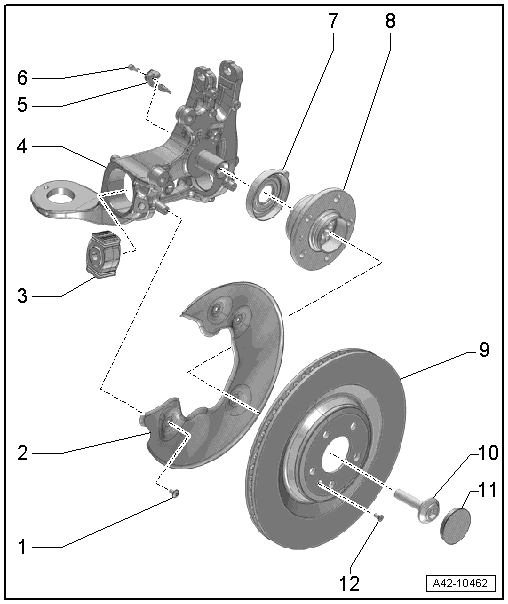
1 - Bolt
- 10 Nm
2 - Cover Plate
- For the brake rotor
3 - Bonded Rubber Bushing
- Replacing. Refer to → Chapter "Wheel Bearing Housing Bonded Rubber Bushing, Replacing, AWD Vehicles".
4 - Wheel Bearing Housing
- Removing and installing. Refer to → Chapter "Wheel Bearing Housing, Removing and Installing, FWD Vehicles".
5 - Rear Speed Sensor
- Left Rear ABS Wheel Speed Sensor -G46-
- Right Rear ABS Wheel Speed Sensor -G44-
6 - Bolt
- Tightening specification. Refer to → Brake System; Rep. Gr.45.
7 - Front Seal
8 - Wheel Hub
 Caution
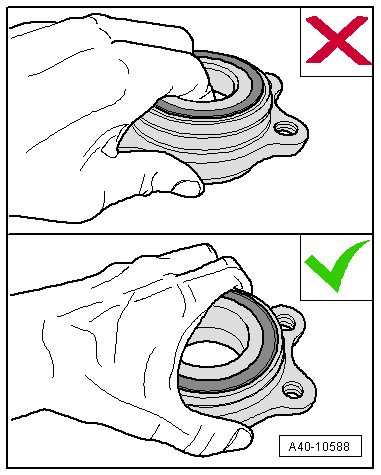
Avoid contaminating with dirt and damaging the seal when setting down/storing. Refer to → Fig. "Avoid Contaminating with Dirt and Damaging the Seal When Setting Down/Storing.".
- Wheel bearing unit, removing and installing. Refer to → Chapter "Wheel Bearing Unit, AWD, Removing and Installing".
- For servicing the wheel bearing unit. Refer to → Chapter "Wheel Bearing Unit, Servicing".
9 - Brake Rotor
10 - Bolt
- 200 Nm +180º turn
- Always replace if removed
- Follow the assembly information when loosening and tightening. Refer to → Chapter "Drive Axle Threaded Connection, Loosening and Tightening".
11 - Dust Cap
12 - Bolt
- Tightening specification. Refer to → Brake System; Rep. Gr.46.
Avoid Contaminating with Dirt and Damaging the Seal When Setting Down/Storing.
- The wheel bearing -1- must always face up.
- Always set the wheel bearing unit down on the wheel hub -2-.
Overview - Wheel Bearing Housing, Vehicles with AWD
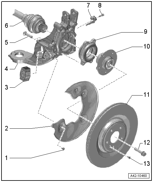
1 - Bolt
- 10 Nm
2 - Cover Plate
- For the brake rotor
3 - Bonded Rubber Bushing
- Replacing. Refer to → Chapter "Wheel Bearing Housing Bonded Rubber Bushing, Replacing, AWD Vehicles".
4 - Wheel Bearing Housing
- Removing and installing. Refer to → Chapter "Wheel Bearing Housing, AWD, Removing and Installing".
5 - Bolt
- 80 Nm +90º turn
- Always replace if removed
6 - drive axle
- There are different versions. Refer to the Parts Catalog.
7 - Rear Speed Sensor
- Left Rear ABS Wheel Speed Sensor -G46-
- Right Rear ABS Wheel Speed Sensor -G44-
8 - Bolt
- Tightening specification. Refer to → Brake System; Rep. Gr.45.
9 - Wheel Bearing
Caution
Avoid contaminating with dirt and damaging the seal when lifting, setting down/storing. Refer to → Fig. "Avoid Contaminating with Dirt and Damaging the Seal When Lifting, Setting Down/Storing.".
- Wheel bearing unit, removing and installing. Refer to → Chapter "Wheel Bearing Unit, AWD, Removing and Installing".
- For servicing the wheel bearing unit. Refer to → Chapter "Wheel Bearing Unit, Servicing".
10 - Wheel Hub
Caution
Avoid contaminating with dirt and damaging the seal when lifting, setting down/storing. Refer to → Fig. "Avoid Contaminating with Dirt and Damaging the Seal When Lifting, Setting Down/Storing.".
- Wheel bearing unit, removing and installing. Refer to → Chapter "Wheel Bearing Unit, AWD, Removing and Installing".
- For servicing the wheel bearing unit. Refer to → Chapter "Wheel Bearing Unit, Servicing".
11 - Brake Rotor
12 - Bolt
- Tightening specification -Item 14-.
13 - Bolt
- Tightening specification. Refer to → Brake System; Rep. Gr.46.
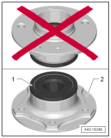
Avoid Contaminating with Dirt and Damaging the Seal When Lifting, Setting Down/Storing.
- The wheel bearing -1- must always face up.
- Always set the wheel bearing down on the wheel hub -2-.
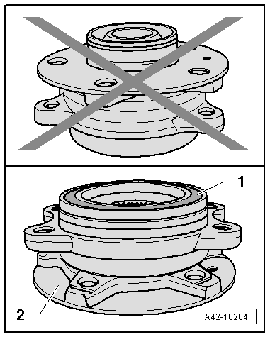
- Never reach into the inside when lifting the wheel bearing.
- Hold the wheel bearing only on the outside.
The same procedure also applies to the wheel bearing without a wheel hub.