Audi A6 Typ 4G: Rear Bumper Cover, Removing and Installing
Bumper Cover, Removing and Installing, Vehicles through MY 2014
Removing
- Remove the bolts -5-.
- Remove the bolts -1, 2 and 3- on the bumper cover side plates -4-.
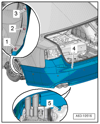
- Remove the cover in the luggage compartment side trim panel.
- Vehicles with a trailer hitch: Remove the cable mount. The cable remains installed in the mount. Refer to → Chapter "Cable Mount, Removing and Installing".
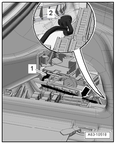
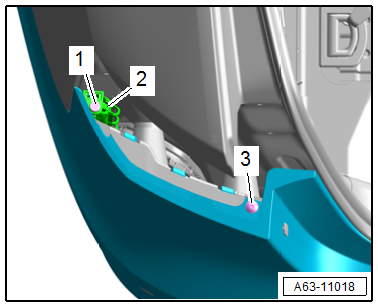
- If equipped, cut the cable tie and disconnect the connector -1- from the Parking Aid Control Module -J446- and free up the wiring harness on the bracket for the control module -arrow-.
- If equipped disconnect the connector for the Rear Lid Opener Control Module -J938-.
- Press the grommet -2- outward.
- Remove the exterior tail lamps. Refer to → Electrical Equipment; Rep. Gr.94; Tail Lamps; Tail Lamp, Removing and Installing.
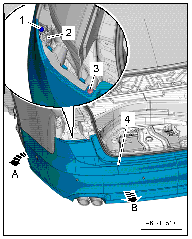
- Remove the bolt -3-.
- Remove the securing pin -1- upward and open the flap -2-.
- Disengage the retainers on the side panel toward the outside -arrow A-.
- Pull the center of the bumper cover -4- to the rear out of the retainer -arrow B-.
- Guide the wiring harness out through the opening in the body, if equipped.
- Remove the bumper cover and lay it on a soft surface.
Installing
Install in reverse order of removal. Note the following:
- Check the gap dimensions. Refer to → Chapter "Bumper Cover Gap Dimension".
Bumper Cover, Removing and Installing, Vehicles from MY 2015
Removing
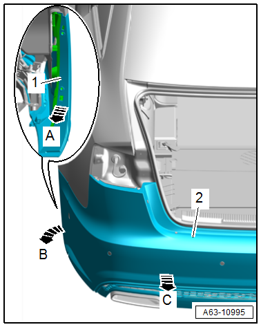
- Remove the bolts -5 and 6-.
- Remove the bolts -1, 2 and 3- on the bumper cover side plates -4-.

- Remove the cover in the luggage compartment side trim panel.
- Disconnect the connector -1-.
- Press the grommet -2- outward.
- Remove the exterior tail lamps. Refer to → Electrical Equipment; Rep. Gr.94; Tail Lamps; Tail Lamp, Removing and Installing.
- Remove the bolt -3-.
- Remove the securing pin -1- upward and open the flap -2-.
- Release the retaining strip -1- sideways from the mount -arrow A.-
- Disengage the retainers on the side panel toward the outside -arrow B-.
- Pull the center of the bumper cover -2- to the rear out of the retainer -arrow C-.
- Guide out the wiring harness from the body guide.
- Remove the bumper cover and lay it on a soft surface.
Installing
Install in reverse order of removal. Note the following:
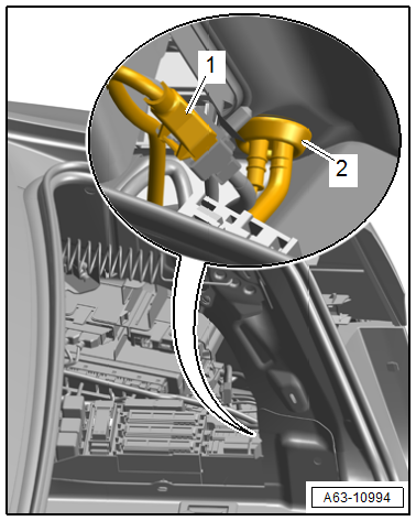
- Check all adjusting mechanisms -2- by turning the adjusting nut -1- slightly -arrows-.
- Rotate the adjusting nuts all the way down but do not tighten.
- Set the bumper cover in the installation position.
- Check the gap dimensions. Refer to → Chapter "Bumper Cover Gap Dimension".
- Tighten the bolts.
 Note
Note
When removing the bolt, the adjusting nut on the adjusting mechanism turns by itself towards the mounting point on the bumper cover and secures it.

Bumper Cover Gap Dimension
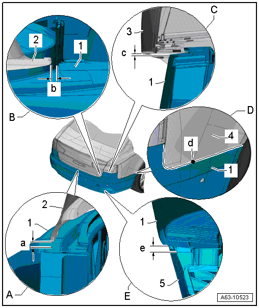
A - Rear Bumper Cover to the Bottom of the Rear Lid
- Gap dimension -a- = 5.0 mm
-1- Bumper cover
-2- Rear lid
B - Rear Bumper Cover to the Side of the Rear Lid
- Gap dimension -b- = 3.5 mm
-1- Bumper cover
-2- Rear lid
C - Rear Bumper Cover to the Outer Tail Lamp
- Gap dimension -c- = 2.5 mm
-1- Bumper cover
-3- Outer tail lamp
D - Rear Bumper Cover to the Rear Side Panel
- Gap dimension -d- = zero gap
-1- Bumper cover
-4- Rear side panel
E - Rear Bumper Cover to the Bumper Cover Lower Section
- Gap dimension -e- = 1.0 mm
-1- Bumper cover
-5- Bumper cover lower section

