Audi A6 Typ 4G: Trailer Hitch
Overview - Outlet, Towing Recognition Control Module
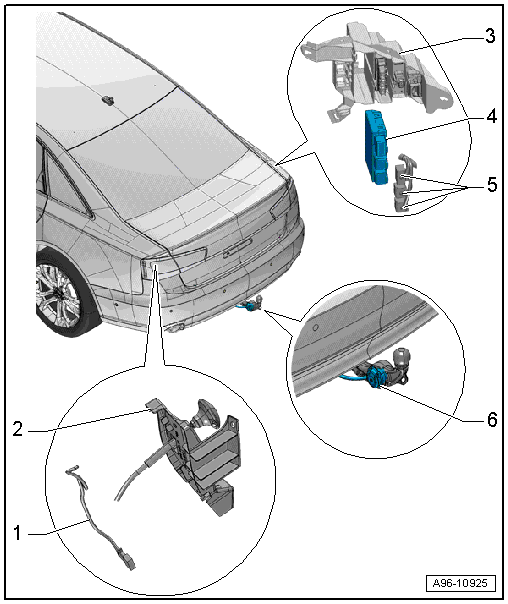
1 - LED Indicator Lamp
- Trailer Hitch -Locked- Indicator Lamp -K226-, Trailer Hitch -Unlocked- Indicator Lamp -K227-
- Make sure the trailer hitch is locked correctly
- Removing and installing. Refer to → Chapter "LED Indicator Lamp, Removing and Installing".
2 - Mount
- For the cable
- For unlocking the trailer hitch
3 - Upper Frame
- For Towing Recognition Control Module -J345-
4 - Towing Recognition Control Module -J345-
- Removing and installing. Refer to → Chapter "Towing Recognition Control Module -J345-, Removing and Installing".
5 - Connectors
6 - Trailer Socket -U10-
- Removing and installing. Refer to → Electrical Equipment General Information; Rep. Gr.96; Trailer Hitch.
- For the connector assignment. Refer to → Electrical Equipment General Information; Rep. Gr.96; Trailer Hitch.
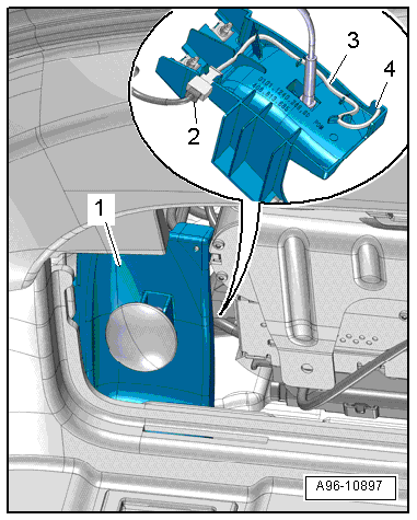
LED Indicator Lamp, Removing and Installing
Removing
- Remove the luggage compartment left side trim panel cover.
- Remove the LED indicator lamp -4- from the cable mount -1- and free up the electric wire -3-.
- Remove the connector -2- from the mount and disconnect it.
Installing
Install in reverse order of removal.
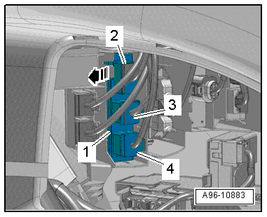
Towing Recognition Control Module -J345-, Removing and Installing
- If the control module was replaced, select the "Replace" function for the respective control module in "Guided Fault Finding" or "Guided Functions" using the Vehicle Diagnostic Tester.
Removing
- Remove the luggage compartment right side trim panel cover.
- Disconnect the connectors -2, 3 and 4-.
- Release the tab in direction of -arrow- and remove the towing recognition control module -1- from the upper retaining frame.
Installing
Install in reverse order of removal.