Audi A6 Typ 4G: Central Valve, Removing and Installing
Removing
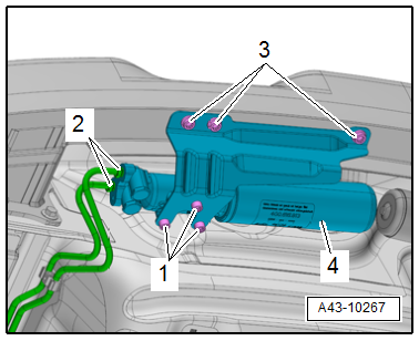
The central valves are attached to the impact member under the bumper cover in the rear.
- Remove the rear bumper cover. Refer to → Body Exterior; Rep. Gr.63; Rear Bumper; Bumper Cover, Removing and Installing.
 WARNING
Always wear safety goggles!
 Note
Note
- The DRC lines must be extracted before disconnecting them from the central valve. Refer to → Chapter "Dynamic Ride Control (DRC), Draining and Filling".
- Perform this step on both wiring harnesses on the central valve.
- Remove the union bolts -2-.
- Unscrew the bolts -1 and 3- and remove the central valve -4-.
Installing
- Install in reverse order of removal. Note the following:
- Install the DRC line connections for the appropriate lines on the central valve.
Fill the DRC system. Refer to → Chapter "Dynamic Ride Control (DRC), Draining and Filling".
Electronic Damping Control Module -J250-, Removing and Installing
The control module is not designed for coding and adaptation when replaced, so the "Replace" function in "Guided Fault Finding" cannot be performed with the Vehicle Diagnostic Tester.
The new Electronic Damping Control Module -J250- can be used right away.
Note
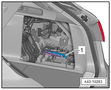
The Electronic Damping Control Module -J250- is installed behind the right side trim panel inside the luggage compartment.
Removing
- Turn off all electrical consumers.
- Remove the cover from the right luggage compartment storage compartment.
- Release and remove the connectors from the control module -1-.
- Remove the control module from its bracket.
Installing
Install in reverse order of removal.