Audi A6 Typ 4G: Magnetic Fields, Setting
It Is Necessary to Set the Magnetic Zone If
- A new Automatic Dimming Interior Rearview Mirror -Y7- is installed.
- If the vehicle is driven a long distance over more than two zones from the originally set zone, then the new zone must be set again.
Magnetic Zone, Setting
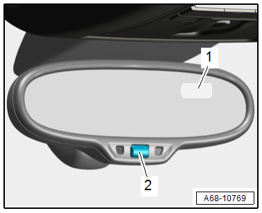
- Press button -2- for six to nine seconds until a "Z" and a magnetic zone number appear.
- Keep pressing the button until the number of the desired zone appears.
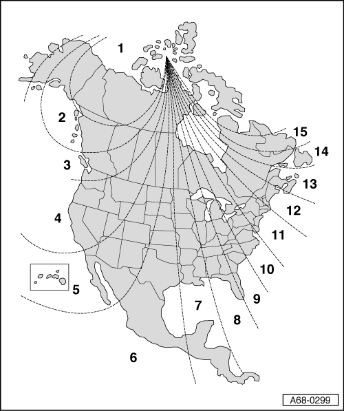
- Read desired magnetic zone on the world map:
- North America.
After a few seconds, the compass display switches from the zone number to the direction.
- The interior rearview mirror automatic dimming function is reactivated after the magnetic zone is set. Refer to → Chapter " Compass Display, Switching On and Off".
Digital Compass, Calibrating
It Is Necessary to Calibrate the Digital Compass If
- The compass directions are not correct,
- The letter "C" instead of a direction will appear or the display will be blank.
- A new Automatic Dimming Interior Rearview Mirror -Y7- is installed.
The Digital Compass May Also Need to Be Calibrated If
- the vehicle battery was reconnected after being disconnected for an extended period,
- A new audio system or audio system component was installed.
Digital Compass, Calibrating
- Turn on the ignition.
- The letter "C" must appear in the compass display -1-.
- If the letter "C" does not appear, press button -2- for 9 to 12 seconds until the "C" appears in the compass display.
- Drive in a circle two to three times at about 10 km/h (5 mph) until a direction is shown in the compass display.
- The interior rearview mirror automatic dimming function is reactivated after the calibration is complete. Refer to → Chapter " Automatic Dimming Function, Switching On and Off".
Automatic Dimming Interior Rearview Mirror, Setting to LHD
It is necessary to set to LHD when:
- A new Automatic Dimming Interior Rearview Mirror -Y7- is installed.
- Press the button -2- for 12 to 15 seconds until an "L" (for LHD vehicles) appears.
- Press the button again; the drive side will be changed.
- The interior rearview mirror automatic dimming function is reactivated after the calibration is complete. Refer to → Chapter " Automatic Dimming Function, Switching On and Off".
Zones, Reading in World Maps
North America
Automatic Dimming Interior Rearview Mirror, Checking Function
To check function, following conditions must be fulfilled:
- Interior rearview mirror installed.
- Ignition switched on.
- Reverse gear not engaged.
- Automatic-dimming function must be switched on, indicator light must come on.
Test Sequence
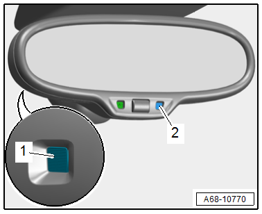
- Cover the photosensor -1- on the housing side.
- Shine a light source, such as a flashlight, on the mirror side of the photosensor -2-.
- The interior rearview mirror must dim within a short period of time.
Special Tools
Special tools and workshop equipment required
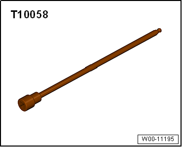
- Hex Ball Socket -T10058-
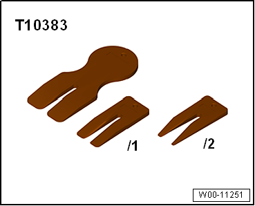
- Wedge Set -T10383-
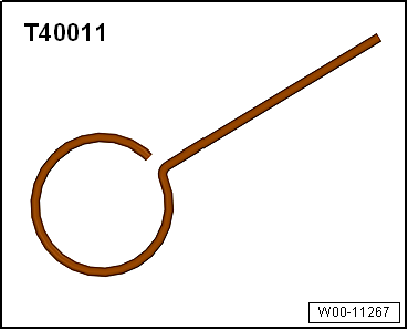
- Locking Pin (3 pc.) -T40011-
- Hook Tool -T40207-

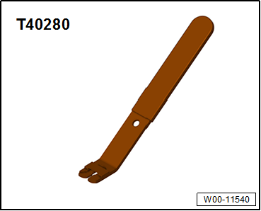
- Omega Clip Tool -T40280-
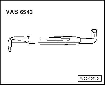
- Angled Screwdriver -VAS6543-
- Pry Lever -80-200-

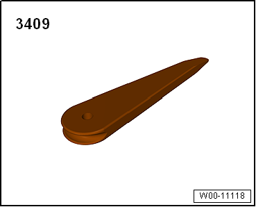
- Trim Removal Wedge -3409-