Audi A6 Typ 4G (2011–2018) Workshop Manual / Chassis / Suspension, Wheels, Steering / Front Suspension / Overview - Drive Axle
Audi A6 Typ 4G: Overview - Drive Axle
- Peened triple roller joint AAR 3300 i with 94 mm outer CV joint
- Peened triple roller joint AAR 3300 i with 98 mm outer CV joint
- Peened triple roller joint AAR 3300 i with 100 mm outer CV joint
- Peened triple roller joint AAR 3300 i with 106 mm outer CV joint
Overview - Drive Axle
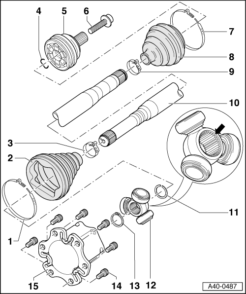
1 - Clamp
- There are different versions depending the type of drive axle
- Always replace if removed
- Tensioning. Refer to → Chapter "Clamp on Triple Roller Joint and Outer Joint, Tensioning".
2 - CV Boot
- If the drive axle has a peened triple roller joint AAR 3300 i, then the triple roller joint has an adapter installed
- Protective joint boot must fit in groove and on joint contour.
3 - Clamp
- There are different versions depending the type of drive axle
- Always replace if removed
- Tensioning. Refer to → Chapter "Clamp on Triple Roller Joint and Outer Joint, Tensioning".
4 - Locking Ring
- Always replace if removed
- Insert before mounting in ring groove (not visible with joint installed)
- Before installing CV joint, align sealing ring in center with opening facing upward.
5 - Outer CV Joint
- Replace only as complete unit.
- For removing.
- Checking.
- For installing.
- For greasing.
- When installing the joint on the profile shaft, the splines on the profile shaft must be lightly coated with grease used in joint.
6 - Bolt
- 200 Nm +180º turn
- Always replace if removed
- Before installing, clean the threads in the CV joint with a tap.
- Follow the sequence when loosening and tightening the threaded connection between the drive axle and the wheel hub. Refer to → Chapter "Drive Axle Threaded Connection, Loosening and Tightening".
7 - Clamp
- Always replace if removed
- Tensioning. Refer to → Chapter "Clamp on Triple Roller Joint and Outer Joint, Tensioning".
8 - CV Boot for Outer CV Joint
- Check for tears and scuffing
9 - Clamp
- Always replace if removed
- Tensioning. Refer to → Chapter "Clamp on Triple Roller Joint and Outer Joint, Tensioning".
10 - Drive Axle
- Removing and installing. Refer to → Chapter "Drive Axle, Removing and Installing".
11 - Locking Ring
- Always replace if removed
- Insert in shaft groove
12 - Triple Roller Star
- Mark installation position before removing
- Disassembling and assembling. Refer to → Chapter "Drive Axle, Disassembling and Assembling"
- When installing triple roller star on axle shaft, splines on axle shaft must be lightly coated with grease used in joint.
13 - Locking Ring
- Always replace if removed
- Insert in shaft groove
14 - Bolt
- Always replace if removed
- Allocation. Refer to the Parts Catalog.
- Tightening specification -Item 22-
15 - Joint
- Disassembling and assembling. Refer to → Chapter "Drive Axle, Disassembling and Assembling"
Grease Quantity and Type
Grease joint when replacing CV boot.
Pack the joint with grease. Refer to the Parts Catalog.
 Note
Note
Note that the outer and inner joints use different types of grease.
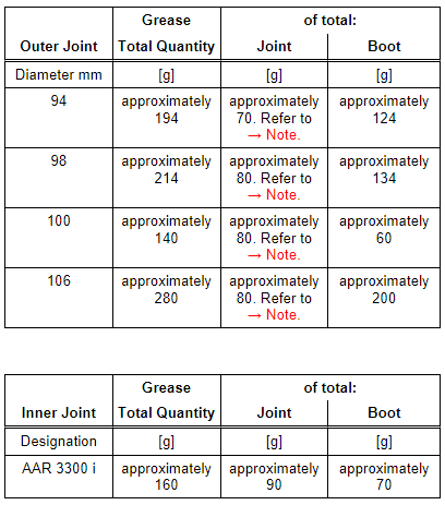
1) This amount goes into the joint through the inner splines on the ball hub. Apply the remainder on the front side of the joint under the boot.

