Audi A6 Typ 4G: Overview - Front Axle, Overview - Subframe
Overview - Front Axle
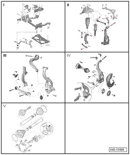
I - → Chapter "Subframe"
II - → Chapter "Suspension Strut and Upper Control Arm"
III - → Chapter "Lower Control Arm and Ball Joint"
IV - → Chapter "Wheel Bearing"
V - → Chapter "Drive Axle"
Overview - Subframe
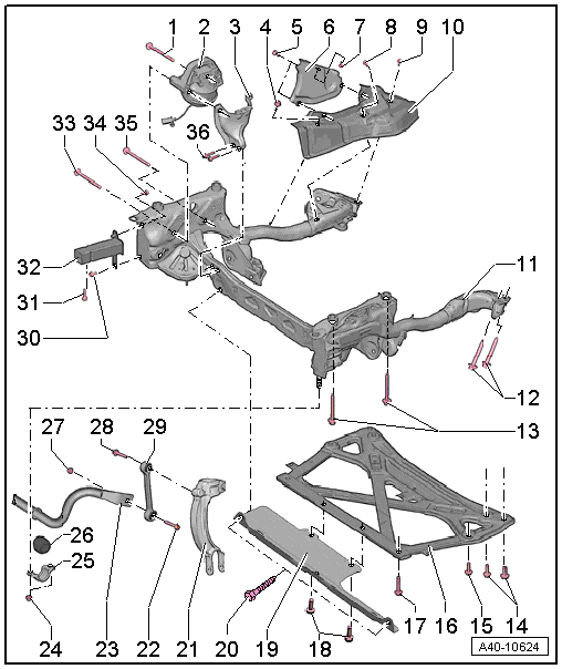
1 - Bolt
- For the tightening specification. Refer to → Engine Mechanical, Fuel Injection and Ignition; Rep. Gr.10; Subframe Mount; Overview - Subframe Mount.
2 - Engine Mount
- Removing and installing. Refer to → Engine Mechanical, Fuel Injection and Ignition; Rep. Gr.10; Subframe Mount; Engine Mount, Removing and Installing.
3 - Engine Mount Bracket
4 - Nut
- 9 Nm
5 - Bolt
- 9 Nm
6 - Heat Shield Upper Section
- Removing and installing. Refer to → Chapter "Subframe Heatshield, Removing and Installing".
7 - Bolt
- 9 Nm
8 - Bolt
- 9 Nm
9 - Bolt
- 9 Nm
10 - Heat Shield Lower Section
- Removing and installing. Refer to → Chapter "Subframe Heatshield, Removing and Installing".
11 - Subframe
- Removing and installing. Refer to → Chapter "Subframe with Steering Gear, Removing and Installing".
 Note
Note
Perform a pre-adjustment on the subframe if it is being replaced or if it had to be removed in order to loosen the crossbrace.
12 - Bolt
- 115 Nm +90º turn
- Always replace if removed
- Remove and tighten diagonally and in steps
13 - Bolt
- 115 Nm +90º turn
- Always replace if removed
- Remove and tighten diagonally and in steps
14 - Bolt
- 90 Nm +180º turn
- Always replace if removed
15 - Bolt
- 90 Nm +180º turn
- Always replace if removed
16 - Subframe Crossbrace
- Removing and installing. Refer to → Chapter "Subframe Crossbrace, Removing and Installing".
 Caution
The suspension components could be damaged.
If the subframe, the steering gear or the subframe crossbrace are not installed correctly, do not rest the vehicle on its wheels.
The vehicle must not be supported on the subframe or the subframe crossbrace (for example using a floor jack).
17 - Bolt
- 90 Nm +180º turn
- Always replace if removed
18 - Bolt
- 20 Nm
19 - Shield
20 - Bolt
- To secure the steering gear, tightening specification. Refer to → Chapter "Overview - Steering Gear, Steering Gear with Tie Rods"
21 - Shock Absorber Fork
22 - Bolt
- 40 Nm +90º turn
- Always replace if removed
- Tighten in the curb weight position. Refer to → Chapter "Wheel Bearing in Control Position, Lifting Vehicles with Air Suspension" or → Chapter "Wheel Bearing in Curb Weight, Lifting Vehicles with Coil Spring".
23 - Stabilizer Bar
- Removing and installing. Refer to → Chapter "Stabilizer Bar, Removing and Installing".
24 - Nut
- 25 Nm
- Always replace if removed
- Remove and install the nuts alternating from side to side
25 - Clamp
26 - Rubber Bushing
- The opening on the rubber bushing must be facing up when installing the subframe.
- There must not be any grease on the stabilizer bar and rubber bushing when installing them.
27 - Nut
- Always replace.
28 - Bolt
- 40 Nm +90º turn
- Always replace if removed
- Tighten in the curb weight position. Refer to → Chapter "Wheel Bearing in Control Position, Lifting Vehicles with Air Suspension" or → Chapter "Wheel Bearing in Curb Weight, Lifting Vehicles with Coil Spring".
29 - Coupling Rod
- Note the installed position. Refer to → Fig. "Installed Location of Connecting Link".
- Removing and installing. Refer to → Chapter "Coupling Rod, Removing and Installing".
30 - Bolt
- 20 Nm
31 - Bolt
- 20 Nm
32 - Front Lower Longitudinal Member
- Installed depending on the engine versions
- Removing and installing. Refer to → Body Exterior; Rep. Gr.63; Front Bumper; Overview - Impact Member.
33 - Bolt
- For attaching the engine mount
- For the tightening specification. Refer to → Engine Mechanical, Fuel Injection and Ignition; Rep. Gr.10; Subframe Mount; Overview - Subframe Mount.
34 - Bolt
- 20 Nm
35 - Bolt
- For attaching the engine mount
- For the tightening specification. Refer to → Engine Mechanical, Fuel Injection and Ignition; Rep. Gr.10; Subframe Mount; Overview - Subframe Mount.
36 - Bolt
- For the tightening specification. Refer to → Engine Mechanical, Fuel Injection and Ignition; Rep. Gr.10; Subframe Mount; Overview - Subframe Mount.
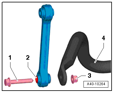
Installed Location of Connecting Link
The left and right coupling rods are identical.
The bolt -1- for connecting the coupling rod to the stabilizer bar -4- must be attached to the "small" surface -2- of the coupling rod collar and secured with the nut -3-.