
Audi A6 Typ 4G (2011–2018) Workshop Manual / Body / Body Interior / Seat Frames / Overview - Front Seat Pneumatic System, Compressor
Audi A6 Typ 4G: Overview - Front Seat Pneumatic System, Compressor
Overview - Compressor, Multi-contour Seat through 08/2012
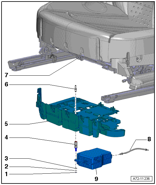
1 - Nut
- 3.5 Nm
- Quantity: 3
- Brace rubber-metal mount while tightening
2 - Spring Washer
- Quantity: 3
3 - Washer
- Quantity: 3
4 - Bonded Rubber Bushing
- Quantity: 3
- Removing and installing. Refer to → Chapter "Multi-contour Seat Compressor Bonded Rubber Bushing, Removing and Installing, through 08/2012".
- Do not install under tension or twisted
5 - Bracket
- For front trim, compressor and Multi-contour seat control module
- Removing and installing. Refer to → Chapter "Front Seat Trim Bracket/Compressor/Control Module, Removing and Installing, Multi-contour Seat".
6 - Rivet
- Quantity: 3
7 - Front Seat
8 - Pneumatic Line
9 - Driver Multi-contour Seat Compressor -V439-
- Front passenger side: Front Passenger Multi-contour Seat Compressor -V440-
- Removing and installing. Refer to → Chapter "Multi-contour Seat Compressors, Removing and Installing, through 08/2012".
Overview - Compressor, Multi-contour Seat from 09/2012
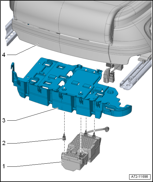
1 - Driver Multi-contour Seat Compressor -V439- with integrated Driver Multi-contour Seat Control Module -J873-
- Front passenger side: Front Passenger Multi-contour Seat Compressor -V440- with integrated Front Passenger Multi-contour Seat Control Module -J872-
- Removing and installing. Refer to → Chapter "Compressor with Integrated Multi-contour Seat Control Module, Removing and Installing, from 09/2012".
2 - Rubber Buffer
- Compressor mount
- Quantity: 4
3 - Bracket
- For front trim, compressor and Multi-contour seat control module
- Removing and installing. Refer to → Chapter "Front Seat Trim Bracket/Compressor/Control Module, Removing and Installing, Multi-contour Seat".
4 - Front Seat

