Audi A6 Typ 4G: Overview - Window Regulator
Overview - Window Regulator
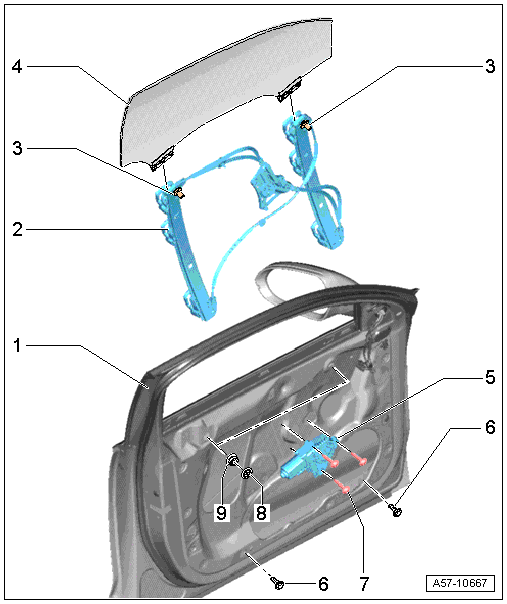
1 - Front Door
2 - Window Regulator
 Note
Note
Vehicles with tinted glass have a different version.
- Removing and installing. Refer to → Chapter "Window Regulator, Removing and Installing".
3 - Threaded Pins
4 - Door Window
Note
Vehicles with tinted glass have a different version.
- Removing and installing. Refer to → Chapter "Front Door Window, Removing and Installing".
5 - Window Regulator Motor
- Removing and installing. Refer to → Chapter "Window Regulator Motor, Removing and Installing".
6 - Bolt
- 6 Nm
7 - Bolt
- 3.5 Nm
8 - Cap
9 - Nut
- 6 Nm
Overview - Window Regulator and Window Regulator Motor
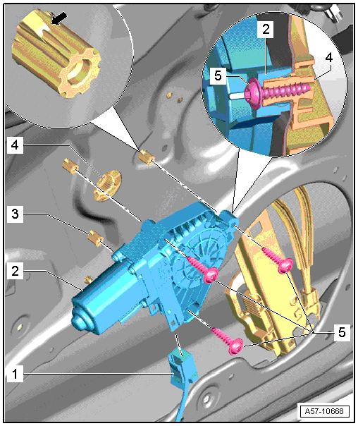
1 - Connector
- Disconnect the connector from the door control module.
2 - Left Window Regulator Motor -V14-
- Removing and installing. Refer to → Chapter "Window Regulator Motor, Removing and Installing".
3 - Threaded Pin
4 - Window Regulator
5 - Bolt
- 3.5 Nm
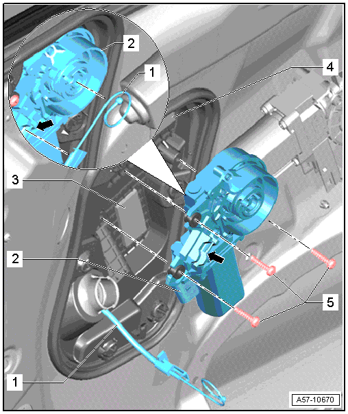
Overview - Exterior Door Handle and Door Lock
Overview - Exterior Door Handle and Door Lock
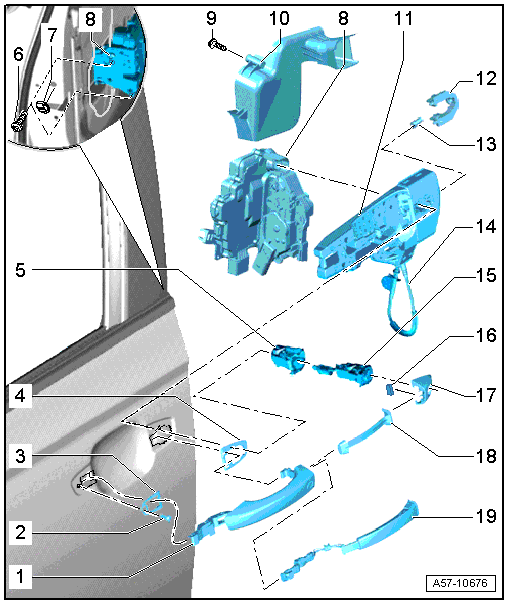
1 - Exterior Door Handle
- Versions: with trim molding, removing and installing. Refer to → Chapter "Door Handle Trim Molding, Removing and Installing ".
- Removing and Installing. Refer to → Chapter "Exterior Door Handle, Removing and Installing".
2 - Bolt
- 2.5 Nm
3 - Front Backing
- Removing and installing. Refer to → Chapter "Exterior Door Handle, Removing and Installing".
4 - Rear Backing
- Removing and installing. Refer to → Chapter "Exterior Door Handle, Removing and Installing".
5 - Housing
- Instead of the lock cylinder
- For the front passenger door
- Removing and installing. Refer to → Chapter "Lock Cylinder, Removing and Installing".
6 - Bolt
- Tightening specification. Refer to → Chapter "Door Lock and Striker Pin Assembly Overview".
7 - Cap
- Pry off
8 - Door Lock
9 - Bolt
- 1.5 Nm
10 - Guide
- For lock cylinder
- Removing and installing. Refer to → Chapter "Lock Cylinder Guide, Removing and Installing".
11 - Bracket
- Remove and install only together with the door lock
- Removing and installing. Refer to → Chapter "Bracket, Removing and Installing".
12 - Bolt
- 2.5 Nm
13 - Retaining Bracket
- For the lock cylinder or housing
- with clamping screw
14 - Operating Cable
- For the door lock
- Removing and installing. Refer to → Chapter "Door Lock Cable, Removing and Installing".
15 - Install the Lock Cylinder
- For the driver door
- Removing and installing. Refer to → Chapter "Lock Cylinder, Removing and Installing".
16 - Magnet
- Only on vehicles with "keyless access authorization system"
- Insert the magnet into the cap.
- Mount the cap on the lock cylinder housing and push it into the door.
- Install the bolt -12- all the way.
17 - Cap
- Driver side: for the lock cylinder
- Front passenger side: closed version
- Versions: with trim molding, removing and installing. Refer to → Chapter "Door Handle Trim Molding, Removing and Installing ".
- Removing and Installing.
18 - Exterior Door Handle Trim
- For vehicles without the "keyless access authorization system"
- Removing and installing. Refer to → Chapter "Exterior Door Handle Trim, Removing and Installing".
19 - Outside Door Handle Sensor
- For vehicles without the "keyless access authorization system"
- Removing and Installing. Refer to → Electrical Equipment; Rep. Gr.94; Access/Start Authorization; Front Exterior Door Handle Switch, Removing and Installing.
Door Lock and Striker Pin Assembly Overview
1 - Door Lock
 Caution
There is a risk of malfunctions.
The door lock must be removed and installed together with the bracket to prevent over-bending the cable when disengaging and engaging it.
The cable must be disconnected from/attached to lever on the door lock outside of the door.
- Removing and installing. Refer to → Chapter "Door Lock, Removing and Installing".
2 - Bolt
- 25 Nm
3 - Catch
- Removing and installing. Refer to → Chapter "Catch, Removing and Installing".
4 - Bolt
- 19 Nm
5 - Grommet
- No replacement part
6 - Inside Door Release Mechanism Cable
- Removing and installing. Refer to → Chapter "Operating Cable for Interior Door Mechanism, Removing and Installing".
7 - Inner Door Panel Cover
- Note different versions
- Removing and installing. Refer to → Chapter "Door Inner Cover, Removing and Installing".
8 - Grommet
- Cannot be replaced separately
9 - Cable for Close Assist
- Only for vehicles with close assist
- Door lock delivery
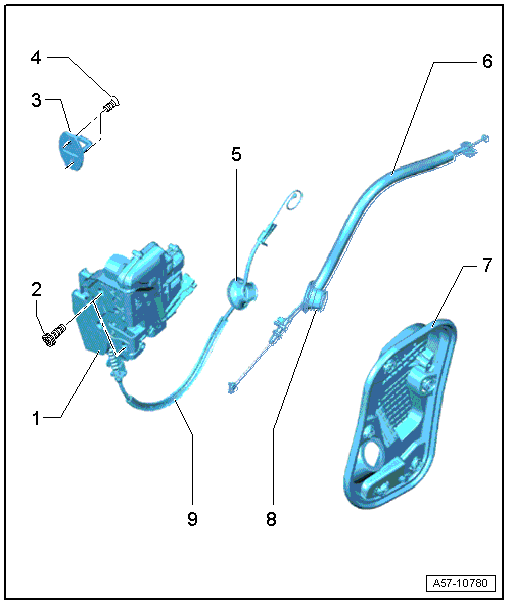
Overview - Door Handle and Door Lock, Door Closing Assist Motor
1 - Release Cable
2 - Driver Door Closing Assist Motor -V302-
- Removing and installing. Refer to → Chapter "Closing Assist Motor, Removing and Installing".
3 - Insulation
4 - Inner Door Panel Cover
5 - Bolt
- 3.5 Nm
Overview - Window Guides and Window Shaft Strips
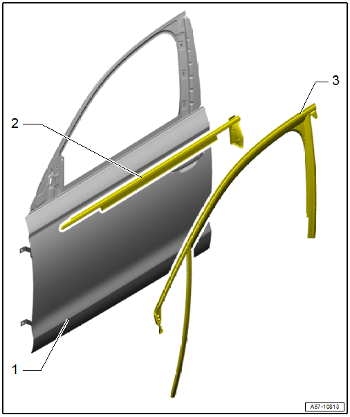
1 - Door
2 - Outer Window Shaft Strip
- Removing and installing. Refer to → Chapter "Outer Window Shaft Strip, Removing and Installing".
3 - Window Guide
- Removing and installing. Refer to → Chapter "Window Guide, Removing and Installing".

