Audi A6 Typ 4G (2011–2018) Workshop Manual / Body / Body Exterior / Rear Doors / Overview - Window Regulator
Audi A6 Typ 4G: Overview - Window Regulator
Overview - Window Regulator

1 - Rear Door
2 - Window Regulator
 Note
Note
Vehicles with tinted glass have a different version.
- Removing and installing. Refer to → Chapter "Window Regulator, Removing and Installing".
3 - Door Window
Note
Vehicles with tinted glass have a different version.
- Removing and installing. Refer to → Chapter "Front Door Window, Removing and Installing".
4 - Threaded Pins
5 - Cap
6 - Nut
- 6 Nm
7 - Left Rear Window Regulator Motor -V26-
- Removing and installing. Refer to → Chapter "Window Regulator Motor, Removing and Installing".
8 - Bolt
- 3.5 Nm
- Quantity: 3
9 - Nut
- 6 Nm
Overview - Window Regulator and Window Regulator Motor
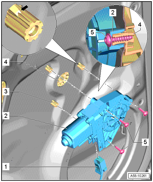
1 - Connector
- Disconnect the connector from the window regulator motor.
2 - Left Rear Window Regulator Motor -V26-
- Removing and installing. Refer to → Chapter "Window Regulator Motor, Removing and Installing".
3 - Threaded Pin
4 - Window Regulator
5 - Bolt
- Tightening specification, -item 8-.

