Audi A6 Typ 4G: Overview - Door Handle and Door Lock
Overview - Door Handle and Door Lock
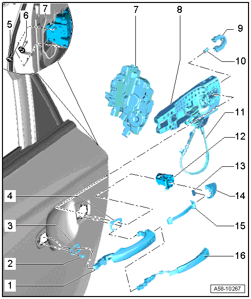
1 - Exterior Door Handle
- Versions: with trim molding, removing and installing. Refer to → Chapter "Door Handle Trim Molding, Removing and Installing ".
- Removing and Installing. Refer to → Chapter "Exterior Door Handle, Removing and Installing".
2 - Bolt
- 2.5 Nm
3 - Front Backing
- Removing and installing. Refer to → Chapter "Exterior Door Handle, Removing and Installing".
4 - Rear Backing
- Removing and installing. Refer to → Chapter "Exterior Door Handle, Removing and Installing".
5 - Bolt
- Tightening specification. Refer to → Chapter "Overview - Door Handle and Door Lock and Operating Cable".
6 - Cap
- Pry off
7 - Door Lock
8 - Bracket
- Remove the door first before removing
- Removing and installing. Refer to → Chapter "Bracket, Removing and Installing".
9 - Retaining Bracket
- For the lock cylinder or housing
- with clamping screw
10 - Bolt
- 2.5 Nm
- Bracket delivery
11 - Operating Cable
- For the door lock
- Removing and installing. Refer to → Chapter "Door Lock Cable, Removing and Installing".
12 - Housing
- Removing and installing. Refer to → Chapter "Housing, Removing and Installing".
13 - Magnet
- Only on vehicles with "keyless access authorization system"
- Insert the magnet into the cap.
- Mount the cap on the lock cylinder housing and push it into the door.
- Install the bolt -12- all the way.
14 - Cap
- Versions: with trim molding, removing and installing. Refer to → Chapter "Door Handle Trim Molding, Removing and Installing ".
- Removing and Installing.
15 - Exterior Door Handle Trim
- For vehicles without the "keyless access authorization system"
- Removing and installing. Refer to → Chapter "Exterior Door Handle Trim, Removing and Installing".
16 - Outside Door Handle Sensor
- For vehicles with the "keyless access authorization system"
- Removing and installing. Refer to → Electrical Equipment; Rep. Gr.94; Access/Start Authorization; Rear Exterior Door Handle Switch, Removing and Installing.
Overview - Door Handle and Door Lock and Operating Cable
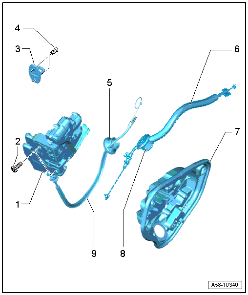
1 - Door Lock
- Removing and installing. Refer to → Chapter "Door Lock, Removing and Installing".
2 - Bolt
- 25 Nm
3 - Catch
- Removing and installing. Refer to → Chapter "Catch, Removing and Installing".
4 - Bolt
- 19 Nm
5 - Grommet
- No replacement part
6 - Inside Door Release Mechanism Cable
- Removing and installing. Refer to → Chapter "Operating Cable for Interior Door Mechanism, Removing and Installing".
7 - Inner Door Panel Cover
- Note different versions
- Removing and installing. Refer to → Chapter "Door Inner Cover, Removing and Installing".
8 - Grommet
- No replacement part
9 - Cable for Close Assist
- Only for vehicles with close assist
- Door lock delivery
Overview - Door Handle and Door Lock, Door Closing Assist Motor

1 - Left Rear Closing Assist Motor -V307-
- Removing and installing. Refer to → Chapter "Closing Assist Motor, Removing and Installing".
2 - Release Cable
3 - Inner Door Panel Cover
4 - Bolt
- 3 Nm
Overview - Window Guides and Window Shaft Strips
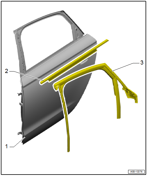
1 - Door
2 - Window Shaft Strip
- Removing and installing. Refer to → Chapter "Window Shaft Strip, Removing and Installing".
3 - Window Guide
- Removing and installing. Refer to → Chapter "Window Guide, Removing and Installing".

