Audi A6 Typ 4G: Rear Final Drive Front Bearing, Replacing, AWD Vehicles
Special tools and workshop equipment required
- Subframe Bushing Tool Kit -3301-
- Bearing Installer - Control Arm -3346-
- Torque Wrench 1332 40-200Nm -VAG1332-
- Engine and Gearbox Jack -VAS6931-
- Hydraulic Press -VAS6178-
- Pneumatic/Hydraulic Foot Pump -VAS6179-
- Bearing Installer - Wheel Hub/Bearing Kit -T10205-
- Hydraulic Press - Ball Joint Assembly Tools -T10254-
- Rear Bushing Tool -T40033-
- Press Piece - Front Final Drive Bushing -T40186-
Removing
 Note
Note
- To replace the rubber bonded bushing, lower the front of the subframe. It is not necessary to remove the subframe.
- Do not lower the subframe more than 4 cm.
Vehicles with Steel Suspension
- Remove the coil springs. Refer to → Chapter "Spring, Removing and Installing, Coil Spring".
Vehicles with Air Suspension
- Bleed the rear axle air spring. Refer to → Chapter "System, Venting or Filling".
Continuation for All Vehicles
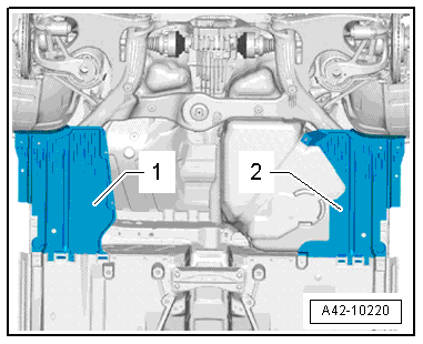
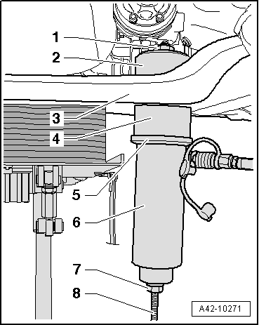
- Remove the underbody covers -1 and 2-. Refer to → Body Exterior; Rep. Gr.66; Underbody Trim Panel; Underbody Panels, Removing and Installing.
- Remove the diagonal braces, if equipped. Refer to → Chapter "Diagonal Braces, Removing and Installing".
- Remove the stone protection plate -2-, where applicable.
Note
Ignore Items -1 and 3-.
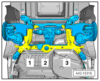
- Place the Engine and Gearbox Jack -VAS6931- under the subframe -1-.
- Place a wood block -2- under the subframe -1-.
- Remove the left and right bolts -arrow-.
- Install the Subframe Lowering Tool -T40253- with the thrust bearing from the Subframe Bushing Tool Kit -3301- and the Subframe Lowering Tool - Nut -T40253/1-, as illustrated, on the opposite side of the bonded rubber bushing being replaced approximately 1.5 cm into the vehicle body.
1 - Subframe Bushing Tool Kit -3301-
2 - Subframe Lowering Tool - Nut -T40253/1-
3 - Subframe Lowering Tool -T40253-
Note
Turn the Subframe Lowering Tool - Nut -T40253/1- on the Subframe Lowering Tool -T40253- until dimension -a- 4 cm is reached.
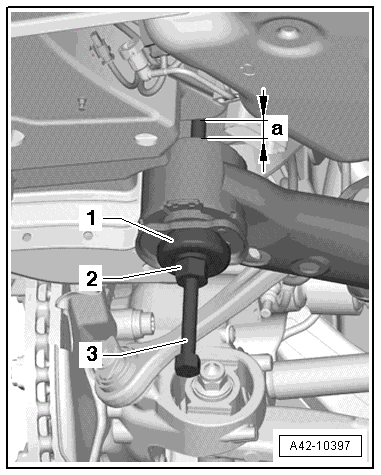
- Remove the bolt -2-.
- Lower the subframe 4 cm only.
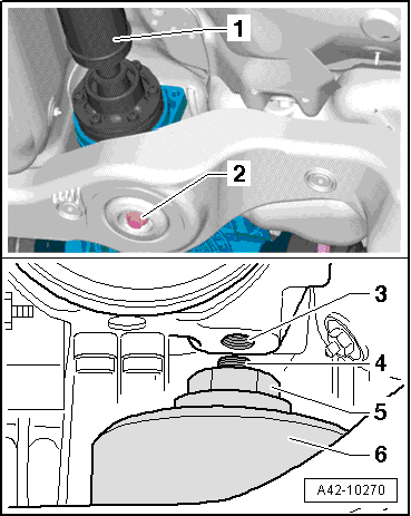
- Push the final drive upward over the drive axle -1-. At the same time insert the Press Piece - Front Final Drive Bushing - Thrust Piece - T40186/1- and the Hydraulic Press - Ball Joint Assembly Tools - Spindle -T10254/5- with the Hydraulic Press - Ball Joint Assembly Tools- Nut -T10254/4-. (A second technician is needed).
4 - Hydraulic Press - Ball Joint Assembly Tools - Spindle -T10254/5- The spindle pins face downward.
5 - Hydraulic Press - Ball Joint Assembly Tools - Nut -T10254/4-
6 - Thrust Piece -T40186/1-
- When removing or installing the rubber bonded bushing, make sure the spindle -4- does not contact the threaded hole -3- in the final drive.
The hold drilled into the inner core of the bonded rubber bushing may prevent the Spindle -T10254/5- from sliding through. If this is the case, it must be drilled out.
Note
- Drill several times in steps using a different drill bit diameter each time.
- While drilling, make sure drill does not damage the threaded hole -3- in the final drive; if necessary place a suitable object in between.
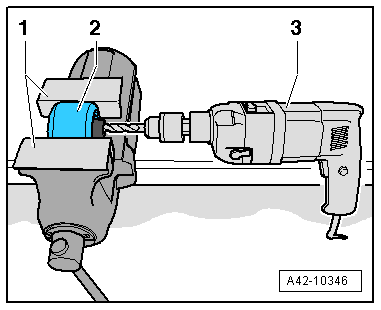
 WARNING
Wear protective eyewear while drilling.
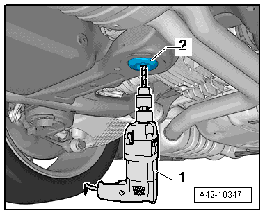
- Position the drill -1- on the bonded rubber bushing -2- as illustrated and drill the hole in several steps.
Step 1, 11 mm drill bit
Step 2, 11.5 mm drill bit
Step 3, 12 mm drill bit
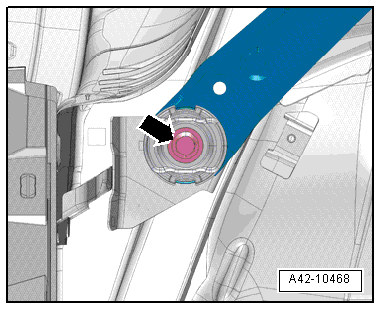
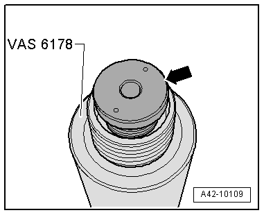
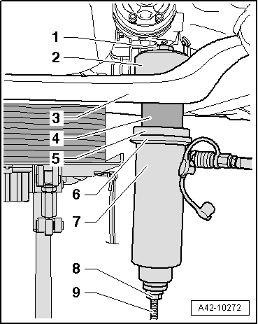
- If necessary, remove the Pressure Head -T10205/13- and in its place install the support with the "small" inner diameter -arrow- from the Hydraulic Press -VAS6178-.
- Place the tools on the front bonded rubber bushing as shown in the illustration.
1 - Hydraulic Press - Ball Joint Assembly Tools - Nut -T10254/4-
2 - Thrust Piece -T40186/1-
3 - Subframe
4 - Rear Bushing Tool - Tube -T40033/3-
5 - Bearing Installer - Wheel Hub/Bearing Kit - 4 -T10205/4-
6 - Hydraulic Press -VAS6178-
7 - Hydraulic Press - Ball Joint Assembly Tools - Nut -T10254/4-
8 - Hydraulic Press - Ball Joint Assembly Tools - Spindle -T10254/5- The spindle pins face downward.
WARNING
- Hold the Hydraulic Press -VAS6178- firmly while pressing out.
- Bonded rubber bushing loosens "abruptly". There is the risk of injuries by tools and bonded rubber bushing coming off!
Installing
Install in reverse order of removal. Note the following:
- Before installing the bonded rubber bushing, make sure the Hydraulic Press - Ball Joint Assembly Tools - Spindle -T10254/5- is able to fit through the hole in the inner core of the bushing. The hold drilled into the inner core of the bonded rubber bushing may prevent the Hydraulic Press - Ball Joint Assembly Tools - Spindle -T10254/5- from sliding through. If this is the case, it must be drilled out.
WARNING
Wear protective eyewear while drilling.
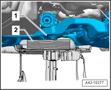
- Gently pre-load the bonded rubber bushing -2- with cover horizontally in the vice clamp as illustrated -1-. Be careful not to damage the outer layer of the bonded rubber bushing.
- Position the drill -3- on the bonded rubber bushing -2- as illustrated and drill the hole in several steps.
1 - Step, 11 mm drill bit
2 - Step, 11.5 mm drill bit
3 - Step, 12 mm drill bit
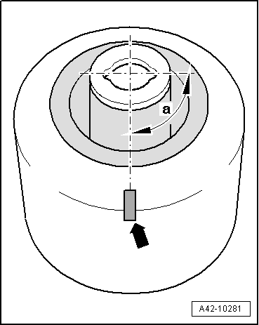
- Make a continuous marking -arrow- straight to the grooves.
a = 90º
Note
- Marking is needed to align bearing with subframe.
- When pulling in the bearing, the grooves are masked by the tool.
- Coat the contact surface of the subframe with grease before installing the bonded rubber bushing. For the correct grease. Refer to the Parts Catalog.
- Install the rubber bonded bushing with the marking -arrow- into the subframe so that the marking points exactly in the driving direction.
- Place the tools on the front bonded rubber bushing as shown in the illustration.
1 - Hydraulic Press - Ball Joint Assembly Tools - Nut -T10254/4-
2 - Press Piece - Carrier Mounting -T40033/7-
3 - Subframe
4 - Bonded rubber bushing
5 - Press Piece - Front Final Drive Bushing - Thrust Plate -T40186/2-
6 - Bearing Installer - Wheel Hub/Bearing Kit - 4 -T10205/4-
7 - Hydraulic Press -VAS6178-
8 - Hydraulic Press - Ball Joint Assembly Tools - Nut -T10254/4-
9 - Hydraulic Press - Ball Joint Assembly Tools - Spindle -T10254/5- The spindle pins face downward.
- Pull bearing into subframe until stop.
Note
If paint damage has occurred during bearing replacement, repair using corrosion protection, primer and black top coat.
Install in reverse order of removal.
- Install the underbody covers. Refer to → Body Exterior; Rep. Gr.66; Underbody Trim Panel; Overview - Underbody Panels.
- Install the diagonal braces. Refer to → Chapter "Diagonal Braces, Removing and Installing".
- Install coil springs. Refer to → Chapter "Spring, Removing and Installing, Coil Spring".
- Fill the rear axle air springs. Refer to → Chapter "System, Venting or Filling".
Rear Final Drive Rear Bearing, Replacing, AWD Vehicles
Special tools and workshop equipment required
- Subframe Bushing Tool Kit -3301-
- Bearing Installer - Control Arm -3346-
- Torque Wrench 1332 40-200Nm -VAG1332-
- Engine and Gearbox Jack -VAS6931-
- Subframe Bushing Assembly Tool -T40185- with the Spindle -T40185/9-
Removing
Note
The rear bonded rubber bushing for the rear final drive can only be pulled out to the rear and pulled in to the front.
- Remove the rear final drive. Refer to → Rear Final Drive 0BC, 0BD, 0BE, 0BF; Rep. Gr.39.
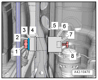
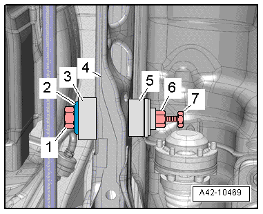
- Attach the tools to the subframe as illustrated.
1 - Bearing Installer - Control Arm - Nut -3346/3-
2 - Subframe Bushing Tool Kit -3301-
3 - Subframe Bushing Assembly Tool - Tube -T40185/2-. Side "A" must face the subframe.
4 - Subframe
5 - Subframe Bushing Assembly Tool - Tube -T40185/1-. Side "A" must face the subframe.
6 - Nut
7 - Spindle -T40185/9-
- Remove the bearing from the subframe while turning at the Nut - Component -3346/3- and counterholding at the Spindle -T40185/9-.
Installing
Install in reverse order of removal. Note the following:
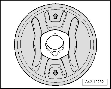
Rear bonded rubber bushing installed position:
- The arrows on the back of the rubber bonded bushing must point up or down.
- Attach the tools and the bonded rubber bushing to the subframe as illustrated.
1 - Bearing Installer - Control Arm - Nut -3346/3-
2 - Subframe Bushing Tool Kit -3301-
3 - Subframe Bushing Assembly Tool - Tube -T40185/1-. Side "A" must face the subframe.
4 - Bonded rubber bushing
5 - Subframe
6 - Subframe Bushing Assembly Tool - Tube -T40185/2-. Side "A" must face the subframe.
7 - Nut
8 - Spindle -T40185/9-
- Install the bearing all the way into the subframe while turning at the Nut - Component -3346/3- and counterholding at the Spindle -T40185/9-.
Note
If paint damage has occurred during bearing replacement, repair using corrosion protection, primer and black top coat.
- Install the rear final drive. Refer to → Rear Final Drive 0BC, 0BD, 0BE, 0BF; Rep. Gr.39.
- Perform a road test. An axle alignment may be necessary. Refer to → Chapter "Subframe, Securing, FWD".
The axle alignment must be performed on a VW/Audi approved alignment stand.