Audi A6 Typ 4G: Rear Seat Pneumatic System, Checking
Preparations for Checking the Lumbar Support Air Cushion for Leaks
Special tools and workshop equipment required
- Pneumatic Repair Set -VAS6618A-
- Vehicle Diagnostic Tester
 Note
Note
- When an appropriate entry is made in the event memory, you are prompted in "Guided Fault Finding" to perform a leak check using the Vehicle Diagnostic Tester.
- Then the preparations for this leak test are described that must be carried out directly in the rear seat.
- For the connection diagram with assignment of the pneumatic lines to the air cushions. Refer to → Chapter "Connection Diagram - Pneumatic System".
Procedure
- Multi-contour seat released in the vehicle and folded forward with electrical harness connectors connected. Refer to → Chapter "Rear Seat Backrest, Removing and Installing, Multi-contour Seat".
- Before disconnecting, mark the assignment of the pneumatic lines to each other using a waterproof permanent marker.
Note
If only one error is displayed for an air cushion, it suffices to disconnect only two pneumatic lines at the described points.
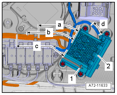
- Disconnect pneumatic lines to the lumbar support air cushions at the following points. Refer to → Chapter "Pneumatic Lines, Disconnecting and Connecting"
- a - 110 mm
- b - 120 mm
- c - 130 mm
Note
Ignore items -1, 2 and d-.
- For checking in the "Guided Fault Finding", connect the air cushion and valve block connections in a diagonal sequence as follows:
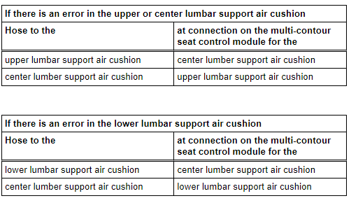
- To connect, attach the Pneumatic Repair Set - Exterior Connector 6x4 -VAS6618/2- to the pneumatic lines.
Note
- To connect, insert the pneumatic lines in the Pneumatic Repair Set - Exterior Connector 6x4 -VAS6618/2- from both sides -A arrows-.
- To release, push release rings in direction of -B arrows- and simultaneously remove pneumatic lines in direction of -C arrows-.
- Connect pneumatic lines following the leak check. Refer to → Chapter "Pneumatic Lines, Disconnecting and Connecting".
Preparations for Checking the Massage Mat Air Cushion for Leaks
Note
- When an appropriate entry is made in the event memory, you are prompted in "Guided Fault Finding" to perform a leak check using the Vehicle Diagnostic Tester.
- Then the preparations for this leak test are described that must be carried out directly in the rear seat.
- For the connection diagram with assignment of the pneumatic lines to the air cushions. Refer to → Chapter "Connection Diagram - Pneumatic System".
Procedure
- Multi-contour seat released in the vehicle and folded forward with electrical harness connectors connected. Refer to → Chapter "Rear Seat Backrest, Removing and Installing, Multi-contour Seat".
- Before disconnecting, mark the pneumatic line assignments to the connections at the valve block using a waterproof permanent marker.
- Disconnect the pneumatic lines for all of the massage mat air cushions.
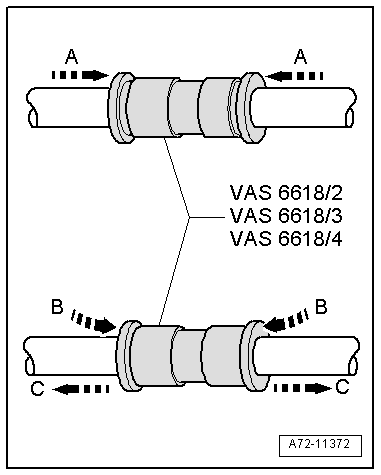
- To do this, press the release ring -2- in the direction of the valve block -1--arrow A- and at the same time pull out the pneumatic line -3--arrow B-.
- To check in the "Guided Fault Finding", remove both of the valve block from the module carrier (refer to → Chapter "Massage Mat Valve Block, Removing and Installing") and reinstall them at their respective opposite sides.
- Connect the connectors.
- Connect the pneumatic lines and check them with a final tug, whether the coupling is locked in correctly.
Preparations for Compressor and Pressure Line Leak Check
Note
- When an appropriate entry is made in the event memory, you are prompted in "Guided Fault Finding" to perform a leak check using the Vehicle Diagnostic Tester.
- Then the preparations for this leak test are described that must be carried out directly in the rear seat.
- For the connection diagram with assignment of the pneumatic lines to the air cushions. Refer to → Chapter "Connection Diagram - Pneumatic System".
Procedure
- Multi-contour seat released in the vehicle and folded forward with electrical harness connectors connected. Refer to → Chapter "Rear Seat Backrest, Removing and Installing, Multi-contour Seat".
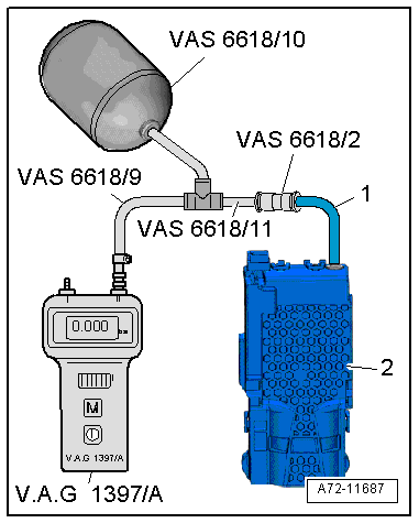
In one of the test steps in the "Guided Fault Finding", you are prompted to connect the Turbocharger Tester Kit -VAG1397A- at the pneumatic line to the Valve Block 2 in Driver Side Rear Seat -N480-/Valve Block 2 in Passenger Side Rear Seat -N482- and Valve Block 3 in Driver Side Rear Seat -N525-/Valve Block 3 in Passenger Side Rear Seat -N526-.
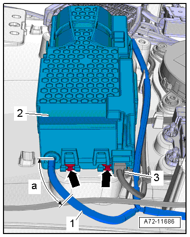
- Disconnect the pneumatic line -1- to the Valve Block 1 in Driver Side Rear Seat -N479-/Valve Block 1 in Passenger Side Rear Seat -N481- at the following position. Refer to → Chapter "Pneumatic Lines, Disconnecting and Connecting".
- a - 30 mm
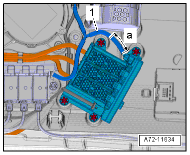
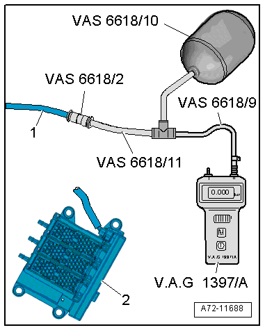
- Using hose and adapter pieces, as well as the Pneumatic Repair Set - Surge Tank -VAS6618/10-, connect the Turbocharger Tester Kit -VAG1397A- with the pneumatic line -1- coming from the compressor.
- To connect, attach the Pneumatic Repair Set - Exterior Connector 6x4 -VAS6618/2- to the pneumatic line.
2 - Valve Block 1 in Driver Side Rear Seat -N479-/Valve Block 1 in Passenger Side Rear Seat -N481-
Note
- To connect, insert the pneumatic lines in the Pneumatic Repair Set - Exterior Connector 6x4 -VAS6618/2- from both sides -A arrows-.
- To release, push release rings -B arrows- and simultaneously remove pneumatic lines -C arrows-.
In one of the test steps in the "Guided Fault Finding", you are prompted to connect the Turbocharger Tester Kit -VAG1397A- at the pneumatic line to the Valve Block 1 in Driver Side Rear Seat -N479-/Valve Block 1 in Passenger Side Rear Seat -N481- and Valve Block 3 in Driver Side Rear Seat -N525-/Valve Block 3 in Passenger Side Rear Seat -N526- or Valve Block 2 in Driver Side Rear Seat -N480-/Valve Block 2 in Passenger Side Rear Seat -N482-.
- Disconnect the pneumatic line -3- to the Valve Block 2 in Driver Side Rear Seat -N480-/Valve Block 2 in Passenger Side Rear Seat -N482- or Valve Block 3 in Driver Side Rear Seat -N525-/Valve Block 3 in Passenger Side Rear Seat -N526--2- at the following position. Refer to → Chapter "Pneumatic Lines, Disconnecting and Connecting".
a - 40 mm
Note
Ignore item -1-.
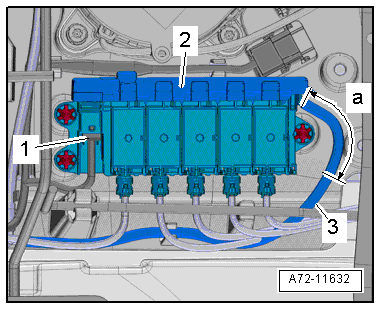
- Using hose and adapter pieces, as well as the Valve Block 1 in Passenger Side Rear Seat -N481-, connect the Turbocharger Tester Kit -VAG1397A- with the pneumatic line -1- coming from the compressor.
- Repeat the check on the pneumatic line coming from the compressor at the opposing valve block.
2 - Valve Block 2 in Driver Side Rear Seat -N480-/Valve Block 2 in Passenger Side Rear Seat -N482- or Valve Block 3 in Driver Side Rear Seat -N525-/Valve Block 3 in Passenger Side Rear Seat -N526-
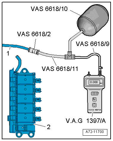
In one of the test steps in the "Guided Fault Finding", you are prompted to connect the Turbocharger Tester Kit -VAG1397A- directly to the compressor.
- Disconnect the pneumatic line -1- to the compressor -2- at the following locations. Refer to → Chapter "Pneumatic Lines, Disconnecting and Connecting".
- a - 50 mm
Note
Ignore item -3 and arrows-.
- Using line and adapter pieces, as well as the Valve Block 1 in Passenger Side Rear Seat -N481-, connect the Turbocharger Tester Kit -VAG1397A- with the pneumatic line -1- for the compressor -2-.
- Connect pneumatic lines following the leak check. Refer to → Chapter "Pneumatic Lines, Disconnecting and Connecting".
Pneumatic Lines, Disconnecting and Connecting
Special tools and workshop equipment required
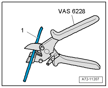
- Hose Cutting Pliers -VAS6228-
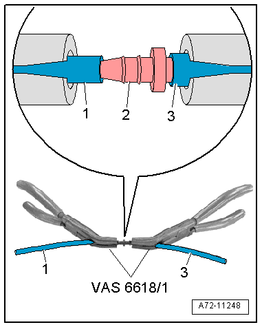
- Pneumatic Repair Set - Pliers -VAS6618/1- (quantity: 2)
Cutting Pneumatic Lines
- Position the Hose Cutting Pliers -VAS6228- at a right angle and cut the pneumatic line -1-.
Connecting Pneumatic Line
- Slide the pneumatic lines -1 and 3- onto the line connector -2- on both sides using the Pneumatic Repair Set - Pliers -VAS6618/1-. Refer to the Parts Catalog.
Pneumatic Lines, Servicing
- A repair kit with pneumatic lines and line connectors is available for the repair of pneumatic lines. Refer to the Parts Catalog.
- Pneumatic lines must not be disconnected directly at the components, only disconnection and connection according to the methods described below is permissible.
- Original replacement parts are delivered with short sections of line to which pneumatic lines with line connectors are connected.
- Protect pneumatic lines and line connectors from soiling.
- Heating the pneumatic lines to connect them to the line connectors is NOT permissible.
- The use of lubricant to connect the pneumatic lines to the line connectors is NOT permissible.
- The repaired pneumatic line is to be exactly as long as the previous line - tolerance +- 10 mm.
- Dirt on the connecting points can cause leaks. Therefore, during tests, make sure the pneumatics and the measuring instruments remain clean.
Compressor with Multi-contour Seat Control Module, Removing and Installing
Removing
 WARNING
- Follow all Safety Precautions when working with pyrotechnic components. Refer to → Chapter "Pyrotechnic Components Safety Precautions".
- Before handling pyrotechnic components (for example, disconnecting the connector), the person handling it must "discharge static electricity". This can be done by touching the door striker, for example.
- Remove the Multi-contour seat. Refer to → Chapter "Rear Seat Backrest, Removing and Installing, Multi-contour Seat".
- Disconnect the connector -3-.
- Remove the compressor -2- sideways out of the rubber buffers (4 pieces) -arrows-.
- Disconnect the pneumatic line -1- to the compressor at the following locations. Refer to → Chapter "Pneumatic Lines, Disconnecting and Connecting".
- a = 50 mm
Installing
- Cut the pneumatic line for the new compressor according to the design of the old compressor.
- Connect the pneumatic line. Refer to → Chapter "Pneumatic Lines, Disconnecting and Connecting".
WARNING
- Follow all Safety Precautions when working with pyrotechnic components. Refer to → Chapter "Pyrotechnic Components Safety Precautions".
- Before handling pyrotechnic components (for example, connecting the connector), the person handling it must "discharge static electricity". This can be done by touching the door striker, for example.
- Observe all measures when installing the Multi-contour seat. Refer to → Chapter "Rear Seat Backrest, Removing and Installing, Multi-contour Seat".
Install in reverse order of removal. Note the following:
Note
The rubber buffer must not be installed under tension or twisted.
Installation notes, for example tightening specifications, replacing components. Refer to → Chapter "Overview - Pneumatic System".

