Audi A6 Typ 4G: Shock Absorber, Removing and Installing
Special tools and workshop equipment required
- Torque Wrench 1331 5-50Nm -VAG1331-
- Torque Wrench 1332 40-200Nm -VAG1332-
- Engine and Gearbox Jack -VAS6931-
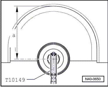
- Engine/Gearbox Jack Adapter - Wheel Hub Support -T10149-
Removing
- Remove the rear wheel. Refer to → Chapter "Wheels and Tires".
- Remove the wheel housing liner. Refer to → Body Exterior; Rep. Gr.66; Wheel Housing Liner; Rear Wheel Housing Liner, Removing and Installing.
- Turn the wheel hub up until a wheel bold hole is on top.
- Attach the Engine/Gearbox Jack Adapter - Wheel Hub Support -T10149- using a wheel bolt as illustrated.
- Insert the Engine/Gearbox Jack Adapter - Wheel Hub Support -T10149- into the Engine and Gearbox Jack -VAS6931- and slightly raise the wheel bearing housing.
 Note
Note
Ignore dimension -a-.
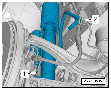
Applies to vehicles with Dynamic Ride Control (DRC)
- Bleed the Dynamic Ride Control (DRC) system. Refer to → Chapter "Dynamic Ride Control (DRC), Draining and Filling".
- In vehicles with switchable DRC and variable damping, remove the connector -1- on the additional component with integrated electric motor from the bracket, disconnect it, and free it up.
- Remove the union bolt -2- and free up the hose line.
- Protect any open connections against dirt.
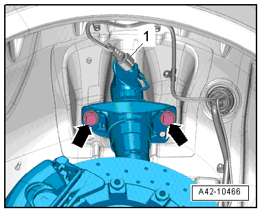
Applies to a Vehicle with Electronically Controlled Damping
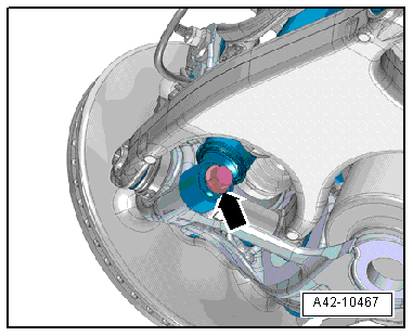
- Disconnect the connector -1- (if equipped).
Continuation for All
- Remove the bolts -arrows-.
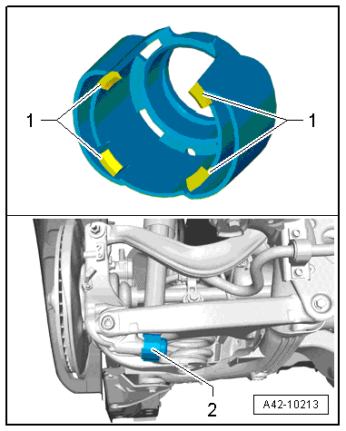
- If it is necessary to replace the shock absorber, release the tabs -1- and remove the stone chip protection -2-.
- Remove the bolt -arrow- and the washer between the wheel bearing housing and the shock absorber.
- Compress the shock absorber as much as possible and remove it.
Installing
Install in reverse order of removal. Note the following:
Note
- Bonded rubber bushings have a limited range of motion. Only tighten suspension bolts when vehicle is in curb weight or control position.
- Wheel bearing, lifting to curb weight position on vehicles with coil springs. Refer to → Chapter "Wheel Bearing in Curb Weight, Lifting Vehicles with Coil Spring".
- For vehicles with air spring suspension, lift wheel suspension in control position. Refer to → Chapter "Wheel Bearing in Control Position, Lifting Vehicles with Air Suspension".
- Install the wheel housing liner. Refer to → Body Exterior; Rep. Gr.66; Wheel Housing Liner; Overview - Rear Wheel Housing Liner.
- Install rear wheel. Refer to → Chapter "Wheels and Tires".
Shock Absorber, Servicing
Shock Absorber, Servicing, Standard Shock Absorber/with DRC System
Special tools and workshop equipment required
- Torque Wrench 1332 40-200Nm -VAG1332-
- Shock Absorber Set -T10001-
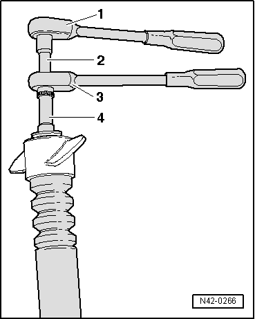
Loosening and Tightening Nut
1 - Ratchet (commercially available)
2 - Shock Absorber Set - Extension with Counter Holder 1 -T10001/9-
3 - Shock Absorber Set - Reversible Ratchet -T10001/11-
4 - Shock Absorber Set - Socket -T10001/1-
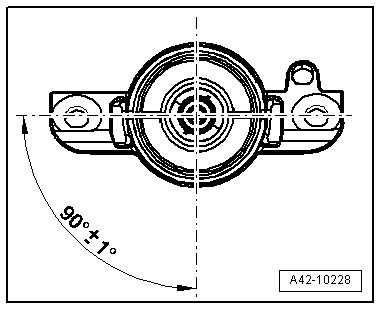
Upper Shock Absorber Mount Installation Position
- Install the upper shock absorber mount so it is rotated 90º to the shock absorber mount.
Shock Absorber, Servicing, Shock Absorber Controlled
Special tools and workshop equipment required
- Torque Wrench 1332 40-200Nm -VAG1332-
- Shock Absorber Set -T10001-
- Counterhold - Shock Absorber - 9mm-T40255-
- Remove the cap -Item 5-.
- Free up the electric wire -arrow- and remove the cap -1- from the upper shock absorber mount.
- Unlock the contacts and remove the connector housing from the electric wire, refer → Electrical Equipment; Rep. Gr.97; Connector Housings, Releasing and Disassemblingto .
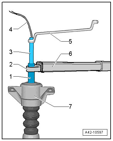
Loosening and Tightening Nut
1 - Shock Absorber Set - Socket -T10001/3-
2 - Torque Wrench 1332 Insert - Ring Wrench - 21mm -VAG1332/7-
3 - Counterhold - Shock Absorber - 9mm -T40255-
4 - Cable
5 - Commercially available wrench
6 - Torque Wrench 1332 40-200Nm -VAG1332-
7 - Shock absorber mount
Upper Shock Absorber Mount Installation Position
- Install the upper shock absorber mount so it is rotated 90º to the lower shock absorber mount.
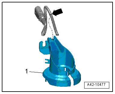
Electric Wire Installed Position on A Shock Absorber with Electronic Damping
- The mark -arrow- on the electric wire must fit into the cap -1- as illustrated.
- Do not bend or twist the electric wire when connecting the connector

