Audi A6 Typ 4G: Subframe Mount
Overview - Subframe Mount
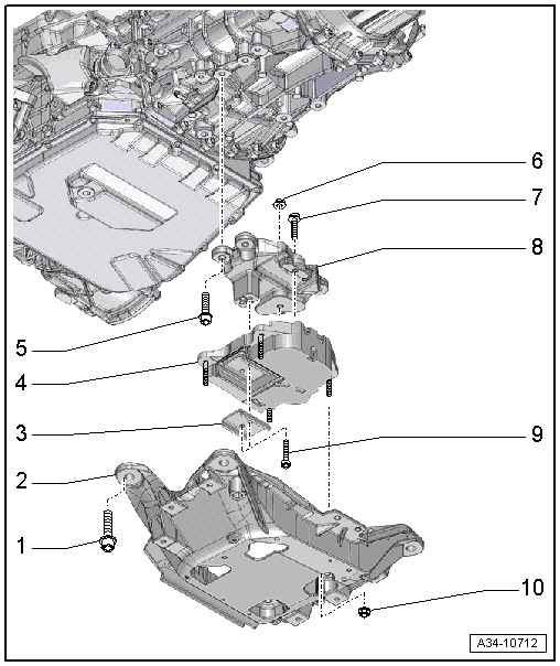
1 - Bolt
- 70 Nm
2 - Tunnel Crossmember
- Removing and installing, refer to → Chapter "Tunnel Crossmember, Removing and Installing".
- Depending on the date of manufacture, an additional air guide for cooling the self-locking center differential is attached to the bottom of the tunnel crossmember. Tightening specification for the air guide section, refer to → Fig. "Air guide -A- "
3 - Stop
- For the transmission mount
4 - Transmission Mount
- Removing and Installing, refer to → Rep. Gr.10; Subframe Mount; Transmission Mount, Removing and Installing.
5 - Bolt
- 40 Nm
6 - Nut
- 20 Nm
7 - Bolt
- 20 Nm
8 - Transmission Support
9 - Bolt
- 20 Nm +90º
- Replacing
10 - Nut
- 20 Nm
Tunnel Crossmember, Removing and Installing
Special tools and workshop equipment required
- Engine and Gearbox Jack -VAS6931-
- Engine/Gearbox Jack - Gearbox Support -T10337-
Removing
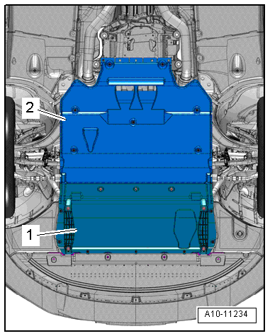
- Remove the rear noise insulation -2-, refer to → Body Exterior; Rep. Gr.66; Noise Insulation; Noise Insulation, Removing and Installing.
- Mount the Engine/Gearbox Jack - Gearbox Support -T10337- on the Engine and Gearbox Jack -VAS6931- and attach it under the transmission.
- Raise the transmission slightly.
 Note
Note
If the tunnel crossmember was removed in or to check or add transmission fluid, then it is necessary to bring the transmission back into its installed position after removing the tunnel crossmember. This is the only way the transmission fluid level can be adjusted correctly, refer to → Chapter "Transmission Fluid Level, Checking".
 WARNING
There is the risk of an accident.
The Engine and Gearbox Jack -VAS6931- may only be used during assembly and must not sit unsupervised under the vehicle.

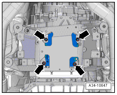
- Remove the bolts from the tunnel crossmember -arrows-.
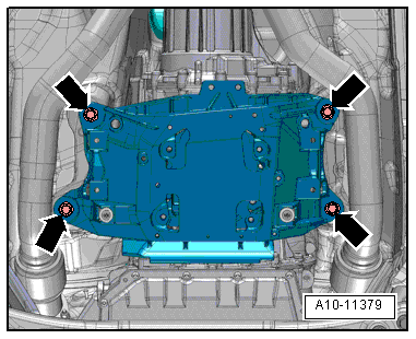
- Remove the nuts -arrows- and the tunnel crossmember.
Installing
Install in reverse order of removal.