Audi A6 Typ 4G: Connection Diagram - Front Seat Pneumatic System
Connection Diagram - Pneumatic System, Multi-contour Seat through 08/2012
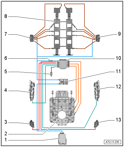
1 - Driver Multi-contour Seat Compressor -V439-
- Front passenger side: Front Passenger Multi-contour Seat Compressor -V440-
2 - Module Carrier with Air Cushions for Lumbar Support
3 - Left Seat Bolster Inflation Adjuster
4 - Left Backrest Bolster Inflation Adjuster
5 - Restrictor
- For exhaust air
- Depending on the version, separate component or integrated in the multi-contour seat control module
- The connection for the restrictor has been removed from the Multi-contour seat control module with an integrated restrictor. Refer to the Parts Catalog.
6 - Check Valve
- Depending on the version, separate component or integrated in the multi-contour seat control module
- Remove the external check valve if installing a Multi-contour seat control module that contains a check valve. Refer to the Parts Catalog.
7 - Valve Block 2 in Driver Seat -N476-
- For massage mat
- Front passenger side: Valve Block 2 in Front Passenger Seat -N478-
8 - Massage Mat
9 - Valve Block 1 in Driver Seat -N475-
- For massage mat
- Front passenger side: Valve Block 1 in Front Passenger Seat -N477-
10 - Driver Multi-contour Seat Control Module -J873-
- Front passenger side: Front Passenger Multi-contour Seat Control Module -J872-
- The connection for the restrictor is deleted on the Original Replacement Part with an integrated check valve and the separate check value must be removed. Refer to the Parts Catalog.
11 - Pulsation Damper
12 - Right Backrest Bolster Inflation Adjuster
13 - Right Seat Bolster Inflation Adjuster
Connection Diagram - Pneumatic System, Multi-contour Seat from 09/2012
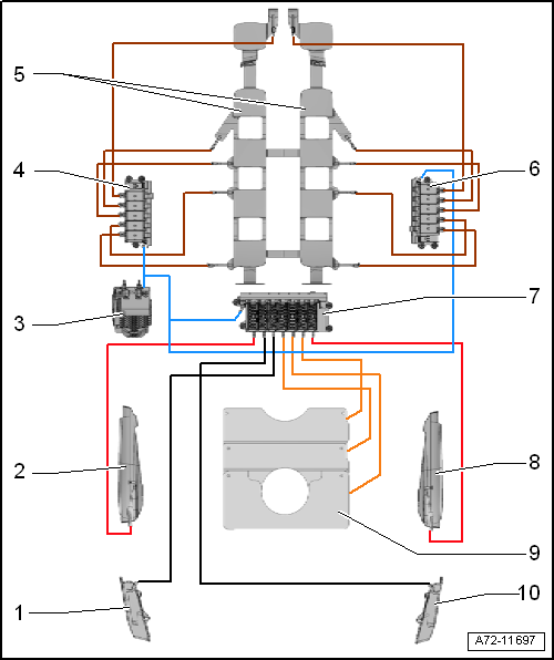
1 - Left Seat Bolster Inflation Adjuster
2 - Left Backrest Bolster Inflation Adjuster
3 - Driver Multi-contour Seat Compressor -V439- with Integrated Driver Multi-contour Seat Control Module -J873-
- Front passenger side: Front Passenger Multi-contour Seat Compressor -V440- with integrated Front Passenger Multi-contour Seat Control Module -J872-
4 - Valve Block 2 in Driver Seat -N476-
- Front passenger side: Valve Block 2 in Front Passenger Seat -N478-
- For massage mat
5 - Massage Mat
6 - Valve Block 3 in Driver Seat -N523-
- Front passenger side: Valve Block 3 in Front Passenger Seat -N524-
- For massage mat
7 - Valve Block 1 in Driver Seat -N475-
- Front passenger side: Valve Block 1 in Front Passenger Seat -N477-
- For lumbar support and side wall adjuster
8 - Right Backrest Bolster Inflation Adjuster
9 - Module Carrier with Air Cushions for Lumbar Support
10 - Right Seat Bolster Inflation Adjuster

