Audi A6 Typ 4G: Control Arm Ball Bearing, Replacing
Control Arm Ball Bearing, Replacing, Wheel Bearing Housing Side
Special tools and workshop equipment required
- Press Plate -VW402-
- Press Piece - Multiple Use -VW412-
- Press Piece - 42mm -VW516-
- Press Piece - Reverse Gear Syncro -3296-
- Assembly Paste -G 052 109 A2-
Procedure
- The control arm is removed. Refer to → Chapter "Control Arm, Removing and Installing".
 Note
Note
Hold track control arm firmly when removing and installing the bonded rubber bushing.
Pressing Out Bonded Rubber Bushing
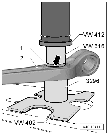
- Mark the press-in depth on the bonded rubber bushing -1--arrow-.
Use a waterproof felt-tip pen for marking.
- Install the special tools as shown in the illustration.
- Remove the bonded rubber bushing -1- from the control arm -2-.
Installing Bonded Rubber Bushing
- Transfer the installation depth marking from the old bonded rubber bushing to the new one.
- Thinly coat the bonded rubber bushing with the Assembly Paste -G 052 109 A2-.
- Install the bonded rubber bushing -1- into the control arm -2-.
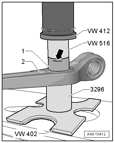
- Install the special tools as shown in the illustration.
Note
When installing, make sure the bonded rubber bushing does not tilt.
- Install the bonded rubber bushing -1- into the control arm -2-.
- Note the installation depth marking when installing -arrow-.
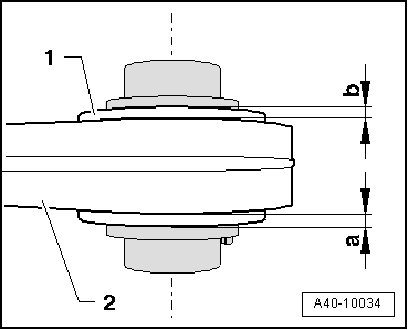
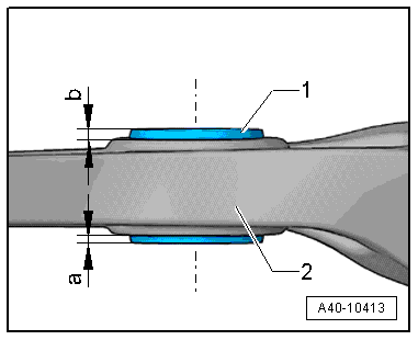
- Check the press-in depth of the bonded rubber bushing -1- inside the control arm -2-.
Dimensions -a and b- must be identical.
- If the dimensions -a and b- are different, adjust the bonded rubber bushing -1-.
- Install the control arm. Refer to → Chapter "Control Arm, Removing and Installing".
Control Arm Ball Bearing, Replacing, Subframe Side
Special tools and workshop equipment required
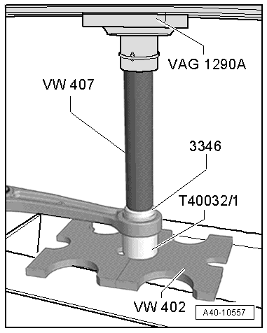
- Shop Press -VAG1290A-
- Press Piece - Rod -VW407-
- Bearing Installer - Control Arm -3346-
- Puller - Differential Bearing -T40032-
- Press Plate -VW402-
- Assembly Paste -G 052 109 A2-
Procedure
- The control arm is removed. Refer to → Chapter "Control Arm, Removing and Installing".
Note
Hold track control arm firmly when removing and installing the bonded rubber bushing.
Pressing Out Bonded Rubber Bushing
- Mark the position of the "kidney" on the bonded rubber bushing on the control arm -arrows- as illustrated.
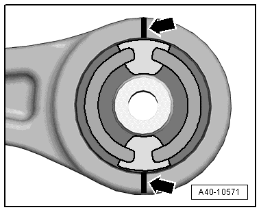
Use a waterproof felt-tip pen for marking.
- Install the special tools as shown in the illustration.
- Remove the bonded rubber bushing from the control arm.
Installing Bonded Rubber Bushing
- Thinly coat the bonded rubber bushing with the Assembly Paste -G 052 109 A2-.
- Install the bonded rubber bushing into the control arm on the side with the bevel -arrow-.
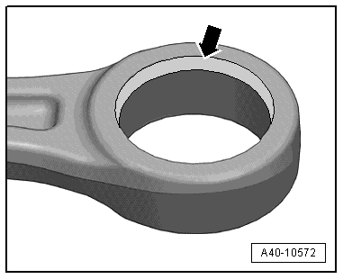
- Align the position of the "kidney" with the markings -arrows- on the control arm made earlier.
- Install the special tools as shown in the illustration.
Note
When installing, make sure the bonded rubber bushing does not tilt.
- Push the bonded rubber bushing into the control arm.
- Check the press-in depth of the bonded rubber bushing -1- inside the control arm -2-.
Dimensions -a and b- must be identical.
- If the dimensions -a and b- are different, adjust the bonded rubber bushing -1-.
- Install the control arm. Refer to → Chapter "Control Arm, Removing and Installing".