Audi A6 Typ 4G: Cupholder, Removing and Installing
Cupholder, Removing and Installing
Removing
- Remove the center console. Refer to → Chapter "Center Console, Removing and Installing".
- Remove the storage compartment in the center console. Refer to → Chapter "Front Center Console Storage Compartment, Removing and Installing".
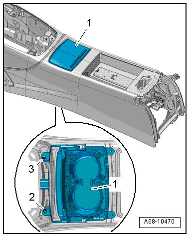
- Remove the screws -2-, -3- and then remove the cupholder -1- downward.
Trim, Removing
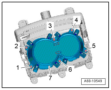
- Remove the screws -1 through 6- and the bracket -7-.
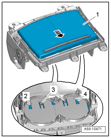
- Lift the retainers -3- by the bottom using a small screwdriver and push the trim in direction of -arrow- at the same time.
- Remove the trim -1- from the cover.
Installing
Install in reverse order of removal. Note the following:
- Attach the trim mounts -2 and 4- to the cover.
Installation notes, for example tightening specifications, replacing components. Refer to → Chapter "Overview - Center Console".
Cupholder, Removing and Installing, Market-Specific
Removing
- Remove the center console rear trim. Refer to → Chapter "Center Console Rear Trim, Removing and Installing".
- Remove the converter with Socket, 12 V-230 V bracket.
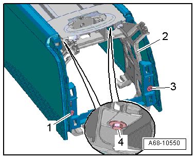
- Remove the bolts -arrows- and remove the cupholder -2- downward from the trim -1-.
- If the cupholder is replaced:
- Free up the wiring harness.
- Remove the cupholder button. Refer to → Electrical Equipment; Rep. Gr.96; Controls; Overview - Center Console Controls.
Installing
Install in reverse order of removal.
Installation notes, for example tightening specifications, replacing components. Refer to → Chapter "Overview - Center Console".
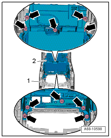
Center Console Bracket, Removing and Installing
Removing
- Remove the center console. Refer to → Chapter "Center Console, Removing and Installing".
Front Bracket
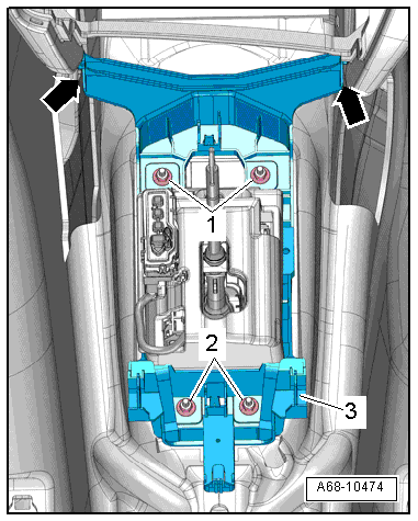
- Remove the Access/Start System Antenna 1 in Vehicle Interior -R138-. Refer to → Electrical Equipment; Rep. Gr.94; Access/Start Authorization.
- Disconnect and free up the connectors.
- Remove the nuts -1 and 2-.
- Disengage the bracket -3- from the tabs -arrows- for the instrument panel and remove it.
Rear Bracket
- Remove the screws -1, 3 and 4-.
- Remove the bracket -2- from the center console downward.
Installing
Install in reverse order of removal. Note the following:
Installation notes, for example tightening specifications, replacing components. Refer to → Chapter "Overview - Center Console".