Audi A6 Typ 4G: Dynamic Steering
Overview - Dynamic Steering
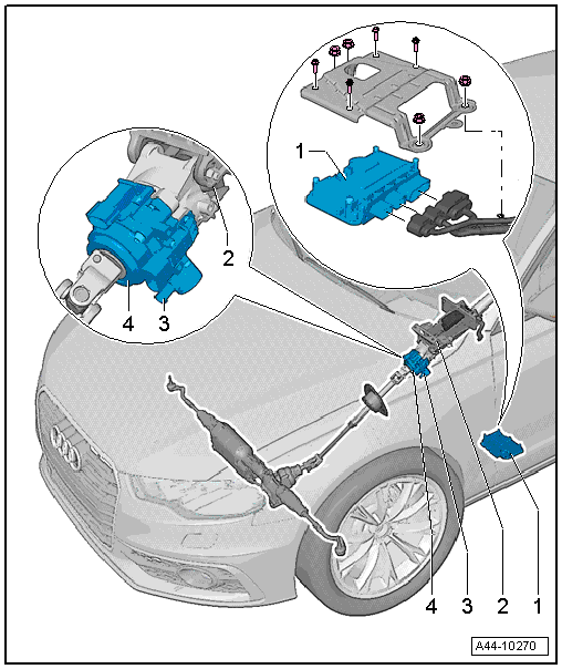
1 - Active Steering Control Module -J792-
- The basic setting must be performed on the system if the Active Steering Control Module -J792- was replaced. Refer to → Chapter "Dynamic Steering Basic Setting".
- Removing and installing. Refer to → Chapter "Active Steering Control Module -J792-, Removing and Installing".
2 - Steering Column
- Removing and installing. Refer to → Chapter "Steering Column, Removing and Installing".
3 - Safety Lock for Active Steering
- Removing and installing. Refer to → Chapter "Active Steering Safety Lock (Locking Magnet), Removing and Installing".
4 - Actuator
- The actuator and steering column are one component and are replaced together.
- Must not be loosened or removed from the steering column.
- Perform a basic setting on the system if the actuator was replaced. Refer to → Chapter "Dynamic Steering Basic Setting".
Active Steering Control Module -J792-, Removing and Installing
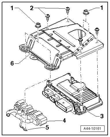
Overview - Active Steering Control Module -J792-
1 - Nut, 2.5 Nm
2 - Bolt, 8 Nm
3 - Active Steering Control Module -J792-
4 - Connector, clipped to the wiring harness
5 - Ground (GND) Wire
6 - Bracket
Special tools and workshop equipment required
- Torque Wrench 1783 - 2-10Nm -VAG1783-
- Vehicle Diagnostic Tester
Removing
The Active Steering Control Module -J792- is located in the footwell in front of the driver seat.
- If the control module is being replaced, then select "replace" control module on the Vehicle Diagnostic Tester in Guided Functions.
- Loosen the driver seat and push it to the rear with the wires still connected. Refer to → Body Interior; Rep. Gr.72; Front Seats; Front Seat, Removing and Installing.
- Remove the floor mat.
- Remove the sill panel strip. Refer to → Body Interior; Rep. Gr.70; Passenger Compartment Trim; Sill Panel Strip, Removing and Installing.
- Remove the foot rest. Refer to → Body Interior; Rep. Gr.70; Passenger Compartment Trim; Foot Rest, Removing and Installing.
- Disengage the floor covering and push it to the side.
- Remove the Night Vision System Control Module -J853- E-box from the stud bolts, if equipped.
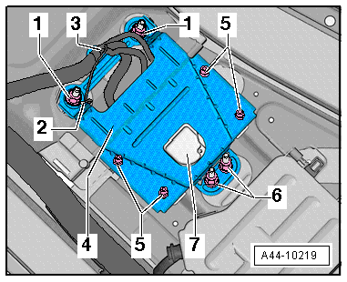
- Remove the nuts -6-.
- Remove the nuts -1- and remove the GND wire -2- from the threaded pin.
- Carefully disconnect the wiring harness clip connection -3- from the bracket -4-.
- Remove the bolts -5- from the control module -7- and remove the bracket -4-.
- Disconnect the wiring harness connector -3- from the control module -7-.
Installing
Install in reverse order of removal. Note the following:
Follow the sequence when installing the control module:
- Attach the bracket -4- to the control module -7- with the bolts -5-.
- Connect the wiring harness connectors -3- to the control module -7-.
- Carefully slide the wiring harness clip connection -3- into the bracket -4-.
- Insert the control module with the bracket.
- Connect the GND wire -2- to the threaded pin and tighten the nuts -1-.
- Tighten the nuts -6-.
- If equipped, place the Night Vision System Control Module -J853- E-box with the 2 pins into the seat crossmember and place the front retainer over the stud bolt.
- The basic setting must be performed on the system if the Active Steering Control Module -J792- was replaced. Refer to → Chapter "Dynamic Steering Basic Setting".
Tightening Specifications
- Active Steering Control Module -J792-.
Dynamic Steering Basic Setting
Special tools and workshop equipment required
- Steering Wheel Scales -VAS6458-
- Vehicle Diagnostic Tester
- Wheel Alignment Computer
There Are Two Choices for Performing a Basic Setting on the Dynamic Steering:
The "Quick Access"
This procedure should be selected for the following activities if only the basic setting will be performed.
- The Active Steering Control Module -J792- was replaced,
- The Steering Angle Sensor -G85- was calibrated,
- The steering column was replaced,
- The steering wheel is at an angle when driving straight.
The "Complete Alignment"
This procedure should be selected for the following activities if a basic setting and a suspension adjustment will be performed.
- The front axle toe was adjusted,
- The rear axle toe was adjusted,
- The vehicle suspension was changed, for example, changing from standard to sport suspension.
 Note
Note
- Both procedures are programmed into the axle alignment computer.
- The respective procedure is performed automatically.
- It is only necessary to select the appropriate program for the procedure that will be performed.
Note
Before starting the basic setting, the Steering Angle Sensor -G85- must be calibrated using the Steering Wheel Scales -VAS6458-.
Preparation Work for Calibrating and Adjusting Driver Assist Systems. Refer to → Chapter "Preparation Work for Calibrating and Adjusting Driver Assist Systems".
- Select the basic setting procedure for dynamic steering in the alignment computer.
- Install the quick clamps on all four wheels.
- Install the measurement sensors on the front and rear wheels.
- Perform wheel run-out compensation. Refer to → Chapter "Wheel Run-Out Compensation".
Note
- Disregard the steering wheel position when doing this.
- Only the display on the alignment computer is valid.
.png)
Perform Any Subsequent Work Using the Vehicle Diagnostic Tester.
- Turn on the ignition.
- Touch Guided Fault Finding on the touch screen.
- Select the following in this order:
- Brand
- Type
- Model year
- Version
- Engine Code
- Confirm the entered data.
Wait until the Vehicle Diagnostic Tester has checked all the vehicle control module.
- Press the GO TO button and select "function/component selection".
- Select the program in Guided Functions.
Follow the instructions on the screen to perform the basic setting.

