Audi A6 Typ 4G: Front Exterior Door Handle Switch, Removing and Installing
Special tools and workshop equipment required
- T-Handle Hook -3438-
Removing
- Remove the exterior door handle. Refer to → Body Exterior; Rep. Gr.57; Door Components; Door Handle, Removing and Installing.
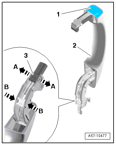
- Release the retaining tabs in direction of -A arrows- and remove the connector -3-.
- Carefully release the retaining hooks in direction of -B arrows- using a small screwdriver and remove the wiring guide.
 Note
Note
Ignore -items 1 and 2-.
- Remove the front exterior door handle illumination bulb, if equipped. Refer to → Chapter "Left/Right Front Exterior Door Handle Illumination Bulb -L162-/-L163-, Removing and Installing".
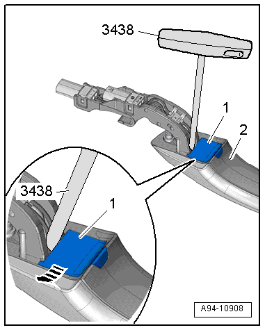
- Unlock the cover -1- on the exterior door handle -2- using the T-Handle Hook -3438-.
- Remove the cover from the exterior door handle in direction of -arrow-.
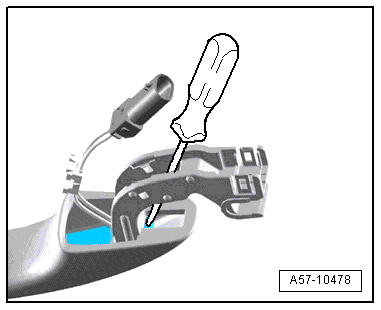
- Position a large stabile screwdriver on the outside door handle as illustrated.
- Remove the exterior door handle touch sensor forward out of the retainer on the exterior door handle using force.
- Remove the outside door handle touch sensor from the handle.
Installing
Install in reverse order of removal. Note the following:
- Slide the outside door handle touch sensor in until it engages audibly.
Rear Exterior Door Handle Switch, Removing and Installing
Special tools and workshop equipment required
- T-Handle Hook -3438-
Removing
- Remove the exterior door handle. Refer to → Body Exterior; Rep. Gr.58; Door Components; Door Handle, Removing and Installing.
- Release the retaining tabs in direction of -A arrows- and remove the connector -3-.
- Carefully release the retaining hooks in direction of -B arrows- using a small screwdriver and remove the wiring guide.
Note
Ignore -items 1 and 2-.
- Remove the rear exterior door handle illumination bulb, if equipped. Refer to → Chapter "Left/Right Rear Exterior Door Handle Illumination Bulb -L168-/-L169-, Removing and Installing".
- Unlock the cover -1- on the exterior door handle -2- using the T-Handle Hook -3438-.
- Remove the cover from the exterior door handle in direction of -arrow-.
- Position a large stabile screwdriver on the outside door handle as illustrated.
- Remove the exterior door handle touch sensor forward out of the retainer on the exterior door handle using force.
- Remove the rear outside door handle touch sensor from the handle.
Installing
Install in reverse order of removal. Note the following:
- Slide the rear outside door handle touch sensor in until it engages audibly.

