
Audi A6 Typ 4G: Overview - Battery
Overview - Battery, Vehicles without High Voltage System

1 - Retaining Bracket
2 - Screw
- 18 Nm
3 - Battery
- Disconnecting and connecting. Refer to → Chapter "Battery, Disconnecting and Connecting, Vehicles without High Voltage System".
- Removing and installing. Refer to → Chapter "Battery, Removing and Installing, Vehicles without High Voltage System".
4 - Screw
5 - Nut
- 5 Nm
6 - Main Fuse Panel
- Disconnecting and connecting. Refer to → Chapter "Battery, Removing and Installing, Vehicles without High Voltage System".
- Overview. Refer to → Chapter "Overview - Relay Carriers, Fuse Panels and E-Boxes".
7 - Negative Terminal Cover
8 - Positive Terminal Cover
9 - Retainer
- For the vehicle tool kit cover
10 - Screw
- 18 Nm
- Quantity: 4
11 - Electrical Wire
- For the Battery Monitoring Control Module -J367-
- Follow the sequence when connecting the ground cable.
12 - Ground Wire with Battery Monitoring Control Module -J367-
- There are different versions. Refer to the Parts Catalog.
- Disconnecting and connecting. Refer to → Chapter "Battery, Disconnecting and Connecting, Vehicles without High Voltage System".
- Removing and installing. Refer to → Chapter "Ground Cable with Battery Monitoring Control Module -J367-, Removing and Installing, Vehicles without High Voltage System".
13 - Nut
- Tightening specification. Refer to → Wiring diagrams, Troubleshooting & Component locations.
14 - Screw
15 - Nut
- 5 Nm
16 - Hose for Central Venting System
17 - Grommet
- For the hose for the central venting system
Overview - Battery -A-, Vehicles with High Voltage System

1 - Retaining Bracket
2 - Screw
- 18 Nm
3 - Battery -A-
- In the luggage compartment in the spare wheel well
- Removing and installing. Refer to → Chapter "Battery -A-, Removing and Installing, Vehicles with High Voltage System".
4 - Fuse Panel A -SA-
- Disconnecting and connecting. Refer to → Chapter "Battery -A-, Removing and Installing, Vehicles with High Voltage System".
- Removing and installing. Refer to → Chapter "Main Fuse Panel in Luggage Compartment, Removing and Installing".
5 - Nut
- 5 Nm
6 - Positive Terminal Cover
7 - Nut
- 5 Nm
8 - Electrical Wire
- For the Battery Monitoring Control Module -J367-
- Follow the sequence when connecting the ground cable.
9 - Battery Bracket
10 - Screw
- 40 Nm
- Quantity: 3
11 - Support Tube
- For the battery bracket
12 - Ground Wire with Battery Monitoring Control Module -J367-
- Disconnecting and connecting. Refer to → Chapter "Battery -A- and Auxiliary Battery -A1-, Disconnecting and Connecting, Vehicles with High Voltage System".
- Removing and installing. Refer to → Chapter "Ground Cable with Battery Monitoring Control Module -J367- for the Battery -A-, Removing and Installing, Vehicles with High Voltage System".
13 - Nut
- 18 Nm
14 - Hose for Central Venting System
Overview - Battery and Auxiliary Battery -A1-, Vehicles with High Voltage System
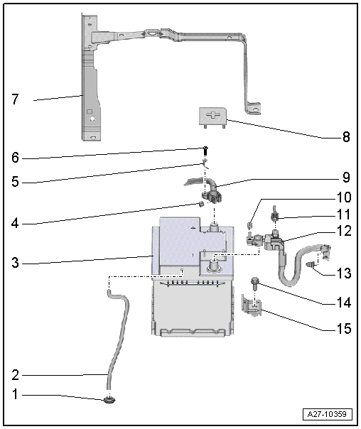
1 - Grommet
- For the hose for the central venting system
2 - Hose for Central Venting System
3 - Auxiliary Battery -A1-
- Removing and installing. Refer to → Chapter "Auxiliary Battery -A1-, Removing and Installing, Vehicles with High Voltage System".
4 - Nut
- 5 Nm
5 - Electrical Wire
6 - Screw
- 3.5 Nm
7 - Battery Bracket
8 - Positive Terminal Cover
9 - Positive Cable
10 - Nut
- 5 Nm
11 - Electrical Wire
- for the Battery Monitoring Control Module 2 -J934-
12 - Ground Wire with Battery Monitoring Control Module 2 -J934-
- Disconnecting and connecting. Refer to → Chapter "Battery -A- and Auxiliary Battery -A1-, Disconnecting and Connecting, Vehicles with High Voltage System".
- Removing and installing. Refer to → Chapter "Ground Cable with Battery Monitoring Control Module 2 -J934- for the Auxiliary Battery -A1-, Removing and Installing, Vehicles with High Voltage System".
13 - Nut
- 18 Nm
14 - Screw
- 9 Nm
15 - Retaining Bracket

