Audi A6 Typ 4G: Parallel Parking Assist
Overview - Parallel Parking Assist
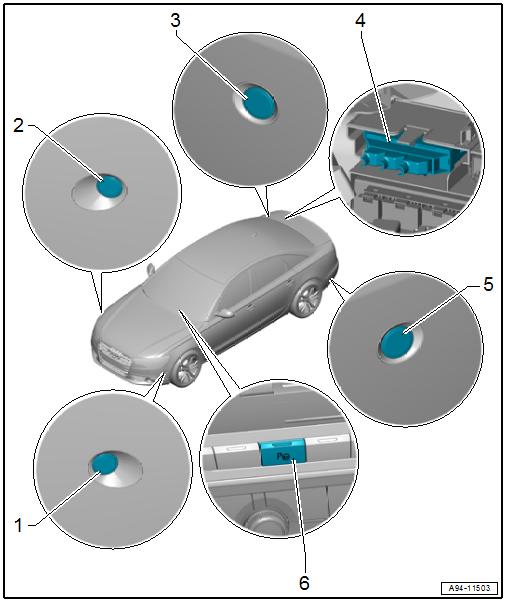
1 - Parallel Parking Assistance Button -E581-
- Removing and installing. Refer to → Chapter "Instrument Panel Button, Removing and Installing".
2 - Right Front Parallel Parking Assistance Sensor -G569-
- Removing and installing. Refer to → Chapter "Front Sensor, Removing and Installing".
3 - Right Rear Parallel Parking Assistance Sensor -G717-
- Removing and installing. Refer to → Chapter "Rear Sensor, Removing and Installing".
4 - Lower Frame
- For the control modules
5 - Parallel Parking Assistance Control Module -J791-
- Integrated in the Parking Aid Control Module -J446-
- Removing and installing. Refer to → Chapter "Parking Aid Control Module -J446-, Removing and Installing".
6 - Left Rear Parallel Parking Assistance Sensor -G716-
- Removing and installing. Refer to → Chapter "Rear Sensor, Removing and Installing".
7 - Left Front Parallel Parking Assistance Sensor -G568-
- Removing and installing. Refer to → Chapter "Front Sensor, Removing and Installing".
Front Sensor, Removing and Installing
Removing
- Remove the front wheel spoiler. Refer to → Body Exterior; Rep. Gr.66; Wheel Housing Liner; Front Wheel Housing Liner, Removing and Installing.
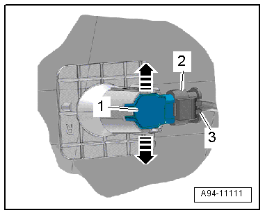
- Press both tabs in direction of -arrows- to the side and press the sensor -1- inward from the outside.
- Disconnect the connector -2- by sliding the retainer -3- back and pressing the release down.
Installing
Install in reverse order of removal.
Rear Sensor, Removing and Installing
Removing
- Remove the rear bumper cover. Refer to → Body Exterior; Rep. Gr.63; Rear Bumper; Bumper Cover, Removing and Installing.
- Press both tabs in direction of -arrows- to the side and press the sensor -1- inward from the outside.
- Disconnect the connector -2- by sliding the retainer -3- back and pressing the release down.
Installing
Install in reverse order of removal. Note the following:
If the bumper cover was removed, the Lane Change Assistance Control Module -J769-/Lane Change Assistance Control Module 2 -J770- must be calibrated again. Refer to → Chapter "Lane Change Assistance, Calibrating".

