Audi A6 Typ 4G: Parallel Parking Assist
Overview - Parallel Parking Assist
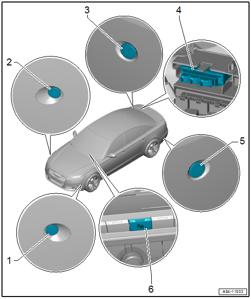
1 - Parallel Parking Assistance Button -E581-
- Removing and installing. Refer to → Chapter "Instrument Panel Button, Removing and Installing".
2 - Right Front Parallel Parking Assistance Sensor -G569-
- Removing and installing. Refer to → Chapter "Front Sensor, Removing and Installing".
3 - Right Rear Parallel Parking Assistance Sensor -G717-
- Removing and installing. Refer to → Chapter "Rear Sensor, Removing and Installing".
4 - Lower Frame
- For the control modules
5 - Parallel Parking Assistance Control Module -J791-
- Integrated in the Parking Aid Control Module -J446-
- Removing and installing. Refer to → Chapter "Parking Aid Control Module -J446-, Removing and Installing".
6 - Left Rear Parallel Parking Assistance Sensor -G716-
- Removing and installing. Refer to → Chapter "Rear Sensor, Removing and Installing".
7 - Left Front Parallel Parking Assistance Sensor -G568-
- Removing and installing. Refer to → Chapter "Front Sensor, Removing and Installing".
Front Sensor, Removing and Installing
Removing
- Remove the front wheel spoiler. Refer to → Body Exterior; Rep. Gr.66; Wheel Housing Liner; Front Wheel Housing Liner, Removing and Installing.
- Press both tabs in direction of -arrows- to the side and press the sensor -1- inward from the outside.
- Disconnect the connector -2- by sliding the retainer -3- back and pressing the release down.
Installing
Install in reverse order of removal.
Rear Sensor, Removing and Installing
Removing
- Remove the rear bumper cover. Refer to → Body Exterior; Rep. Gr.63; Rear Bumper; Bumper Cover, Removing and Installing.
- Press both tabs in direction of -arrows- to the side and press the sensor -1- inward from the outside.
- Disconnect the connector -2- by sliding the retainer -3- back and pressing the release down.
Installing
Install in reverse order of removal. Note the following:
If the bumper cover was removed, the Lane Change Assistance Control Module -J769-/Lane Change Assistance Control Module 2 -J770- must be calibrated again. Refer to → Chapter "Lane Change Assistance, Calibrating".
Automatic Headlamp Range Control
Overview - Automatic Head Lamp Range Control
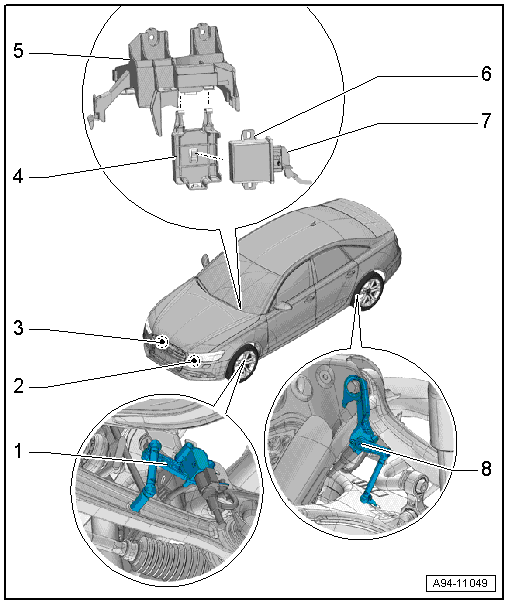
1 - Left Front Level Control System Sensor -G78-
- Component location: on the front control arm
- Removing and installing. Refer to → Suspension, Wheels, Steering; Rep. Gr.43; Level Control System Sensor; Left/Right Front Level Control System Sensor G78/G289, Removing and Installing.
2 - Left Headlamp Beam Adjustment Motor -V48-
- Removing and installing. Refer to → Chapter "Left/Right Headlamp Beam Adjustment Motor -V48-/-V49-, Removing and Installing".
3 - Right Headlamp Beam Adjustment Motor -V49-
- Removing and installing. Refer to → Chapter "Left/Right Headlamp Beam Adjustment Motor -V48-/-V49-, Removing and Installing".
4 - Mount
- for Headlamp Range Control Module -J431- /Cornering Lamp and Headlamp Range Control Module -J745-
- Removing and installing. Refer to → Chapter "Relay Panel Mount, Removing and Installing, Under Instrument Panel and Left Side, Vehicle Electrical System Control Module -J519-".
5 - Mount
- For the Vehicle Electrical System Control Module -J519- and the relay panel under the instrument panel on the left side
- Overview. Refer to → Chapter "Overview - Relay Carrier, Instrument Panel, E-Boxes Fuse Carrier".
6 - Headlamp Range Control Module -J431- /Cornering Lamp and Headlamp Range Control Module -J745-
- Removing and installing. Refer to → Chapter "Headlamp Range Control Module, Removing and Installing".
7 - Connector
8 - Left Rear Level Control System Sensor -G76-
- Component location: on the rear control arm
- Removing and installing. Refer to → Suspension, Wheels, Steering; Rep. Gr.43; Level Control System Sensor; Left/Right Rear Level Control System Sensor G76/G77, Removing and Installing.
Headlamp Range Control Module, Removing and Installing
- If the control module was replaced, select the "Replace" function for the respective control module in "Guided Fault Finding" or "Guided Functions" using the Vehicle Diagnostic Tester.
Removing
- Remove the driver side instrument panel cover. Refer to → Body Interior; Rep. Gr.68; Storage Compartments and Covers; Driver Side Instrument Panel Cover, Removing and Installing.
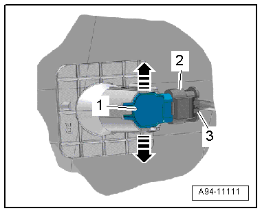
- Open the tab in direction of -arrow A- and remove the control module -2- from the mount -1- in direction of -arrow B-.
- Disconnect the connector -3-.
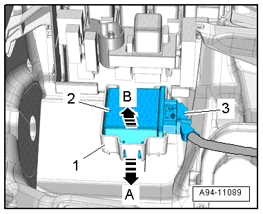
- To disconnect the connector, press the tab -1-, turn the retaining bracket in direction of the -arrow- and remove the connector.
Installing
Install in reverse order of removal.

Special Tools
Special tools and workshop equipment required
- Spark Plug Pliers -VAG1922-
- Headlamp Adjusting Unit -VAS5209B-
- Headlamp Adjusting Unit -VAS621001-
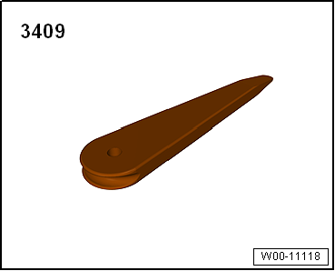
- Trim Removal Wedge -3409-
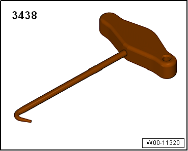
- T-Handle Hook -3438-