Audi A6 Typ 4G: Overview - Suspension Strut, Shock Absorber and Spring
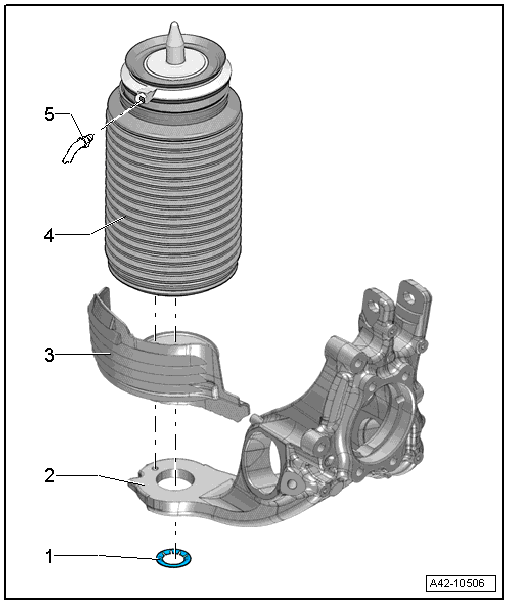
Overview - Suspension Strut, Shock Absorber and Spring, Coil Spring
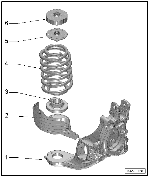
1 - Wheel Bearing Housing
2 - Stone Chip Protection
3 - Lower Spring Plate
- Note the installed position. Refer to → Fig. "Lower Spring Plate Installed Position".
4 - Coil Spring
- Note the installed position. Refer to → Fig. "Coil Spring Installed Position".
5 - Spacer Piece
- Not installed on all vehicles. For the correct allocation. Refer to the Parts Catalog.
6 - Upper Spring Plate
- Vehicles with an upper eccentric spring plate. Refer to → Fig. "Upper Eccentric Spring Plate Installed Position"; for the correct allocation. Refer to the Parts Catalog.
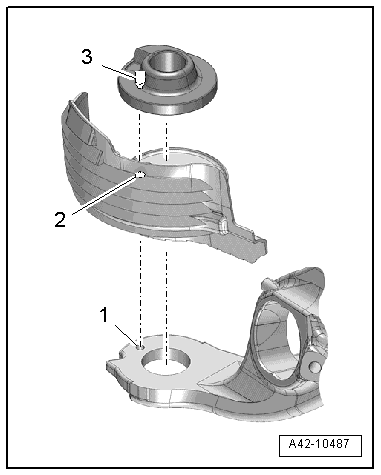
Lower Spring Plate Installed Position
- The centering pin -3- on the lower spring plate must fit into the hole -2- in the stone chip protection and into the hole -1- in the wheel bearing housing.
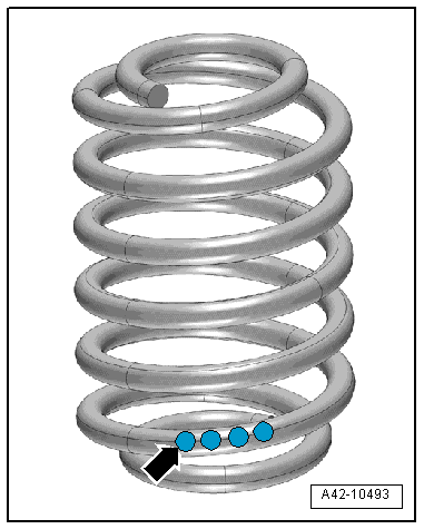
Coil Spring Installed Position
- Lower color marking -arrow-.
- Turn the end of the spring all the way to the lower spring plate.
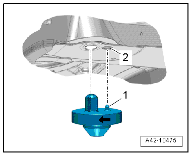
Upper Eccentric Spring Plate Installed Position
- The -arrow- indicates direction of travel.
- The centering pin -1- fit into the longitudinal member -2-.
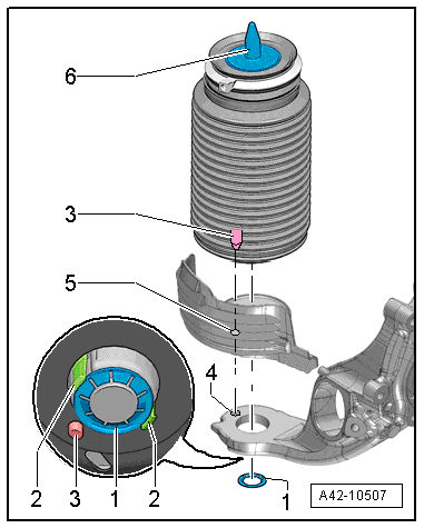
Overview - Suspension Strut, Shock Absorber and Spring, Air Spring
1 - Spring Washer
2 - Wheel Bearing Housing
3 - Stone Chip Protection
4 - Air Spring
- Removing and installing. Refer to → Chapter "Spring, Removing and Installing, Air Spring".
- Note installed position. Refer to → Fig. "Air Spring Installed Position".
5 - Air line
- Tightening specification for the connector -Item 3-
Air Spring Installed Position
- The positioning pin -3- on the air spring must fit into the hole -5- in the stone chip protection and into the hole -4- in the wheel bearing housing.
- The hooks -2- must lock onto the lower wheel bearing housing.
- The spring washer -1- must be pushed on parallel up to the base of the air spring.
- The positioning pin -6- on the air spring must be installed correctly inside the body.
Overview - Suspension Strut, Shock Absorber and Spring, Shock Absorber
Conventional Shock Absorber
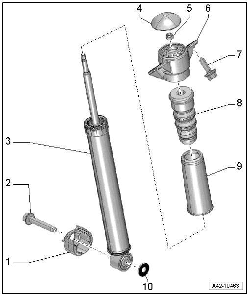
1 - Stone Chip Protection
2 - Bolt
- 150 Nm +180º turn
- Always replace if removed
- Must be tightened in the curb weight position. Refer to → Chapter "Wheel Bearing in Curb Weight, Lifting Vehicles with Coil Spring".
3 - Shock Absorber
- Because of different shock absorber valve systems, only install new shock absorbers from the same manufacturer on both axles.
- Removing and Installing. Refer to → Chapter "Shock Absorber, Removing and Installing".
- Servicing. Refer to → Chapter "Shock Absorber, Servicing, Standard Shock Absorber/with DRC System".
4 - Protective Cap
5 - Nut
- 35 Nm
- Always replace if removed
6 - Upper Shock Absorber Mount
7 - Bolt
- 50 Nm +90º turn
- Always replace if removed
8 - Stop Buffer
9 - Protective Sleeve
10 - Washer
- Serves as corrosion protection
- Always use
Shock Absorber with Electronic Damping
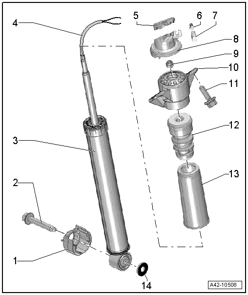
1 - Stone Chip Protection
2 - Bolt
- 150 Nm +180º turn
- Always replace if removed
- Must be tightened in the curb weight position. Refer to → Chapter "Wheel Bearing in Curb Weight, Lifting Vehicles with Coil Spring".
3 - Shock Absorber
- Removing and installing. Refer to → Chapter "Shock Absorber, Removing and Installing".
- Servicing. Refer to → Chapter "Shock Absorber, Servicing, Standard Shock Absorber/with DRC System".
4 - Cable
5 - Protective Cap
6 - Seal
- For the connector
7 - Connector Housing
- Do not bend or twist the electric wire when connecting the connector
8 - Protective Cap
9 - Nut
- 50 Nm
- Always replace if removed
10 - Upper Shock Absorber Mount
11 - Bolt
- 50 Nm +90º turn
- Always replace if removed
12 - Stop Buffer
13 - Protective Sleeve
14 - Washer
- Serves as corrosion protection
- Always use
Shock Absorber with Dynamic Ride Control (DRC) System
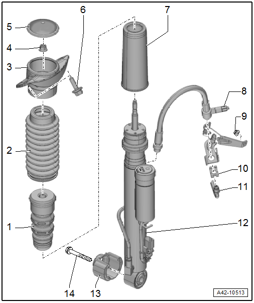
1 - Stop Buffer
2 - Protective Sleeve
3 - Shock Absorber Mount
4 - Nut
- 35 Nm
- Always replace if removed
5 - Protective Cap
6 - Bolt
- 50 Nm +90º turn
- Always replace if removed
7 - Protective Sleeve
8 - Suction/Fill Valve with Hose Line
- Make sure not under tension when installing
9 - Nut
- 9 Nm
10 - Clip
11 - Bolt
- 14 Nm
- Always replace if removed
12 - Shock Absorber
- For the Dynamic Ride Control (DRC) system
- Removing and installing. Refer to → Chapter "Shock Absorber, Removing and Installing".
- Servicing. Refer to → Chapter "Shock Absorber, Servicing, Standard Shock Absorber/with DRC System".
13 - Stone Chip Protection
14 - Bolt
- 150 Nm +180º turn
- Always replace if removed
- Must be tightened in the curb weight position. Refer to → Chapter "Wheel Bearing in Curb Weight, Lifting Vehicles with Coil Spring".

