Audi A6 Typ 4G: Rear Seat Backrest Locking Mechanism, Removing and Installing
Rear Seat Backrest Locking Mechanism, Removing and Installing
Removing
- Remove the rear seat backrest. Refer to → Chapter "Divided Rear Seat Backrest, Removing and Installing".
- Remove the headrest. Refer to → Chapter "Headrest, Removing and Installing".
- Remove the padding on the rear seat backrest around the locking mechanism. Refer to → Chapter "Cover and Cushion, Removing and Installing, Divided Rear Seat Backrest".
Vehicles with Backrest Release
 Note
Note
- The procedure for removing and installing the release cable is described on the left lock to the connector station.
- The connector station lock release cable can only be replaced with the cover and cushion removed.
- Remove the bracket -5- for the release cable on the rear seat backrest.
- Remove the release cable -1- from the locking mechanism -2- in direction of -arrow A-.
- Remove the release cable nipple -4- from the release handle -3- in direction of -arrow B- and remove the release cable.
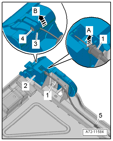
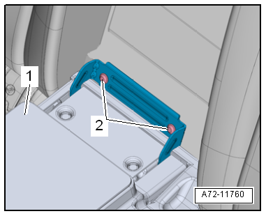
Procedure for All Seat Versions
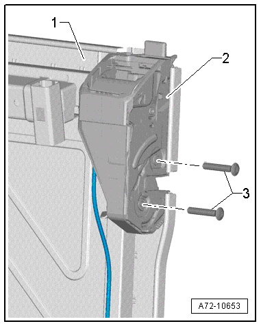
- Remove the bolts -3-.
- Remove the locking mechanism -2- from the rear seat backrest frame -1-.
Installing
Install in reverse order of removal. Note the following:
Installation notes, for example tightening specifications, replacing components. Refer to → Chapter "Overview - Locking Mechanism".
Rear Seat Backrest Release, Removing and Installing
Special tools and workshop equipment required
- Trim Removal Wedge -3409-
Removing
- Remove the luggage compartment lamp. Refer to → Electrical Equipment; Rep. Gr.96; Lamps; Luggage Compartment Lamp W3, Removing and Installing.
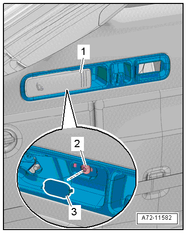
- Pull the release lever -1- (this will release the rear seat backrest) and keep it held.
- Remove the cap -3- with a screwdriver and remove the bolts -2- in the rear for the release.
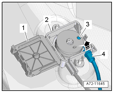
- Remove the rear release -1- with the Trim Removal Wedge -3409- beginning from the luggage compartment side trim panel in direction of -arrow-.
- To do this, release the tabs -2 to 5- with a screwdriver.
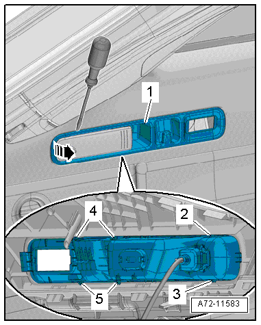
- Unclip the release cable -4- at the release -3- for the backrest release in direction of -arrow-.
- Remove the release cable nipple -1- on the release lever -2- and remove the release.
Installing
Install in reverse order of removal.
Installation notes, for example tightening specifications, replacing components. Refer to → Chapter "Overview - Locking Mechanism, Avant".
Rear Seat Backrest Release Cable/Connector Station, Removing and Installing
Removing
- Remove the rear bench seat. Refer to → Chapter "Seat Bench/Single Seat, Removing and Installing".
- Remove the luggage compartment side trim. Refer to → Chapter "Luggage Compartment Side Trim Panel, Removing and Installing, Avant".
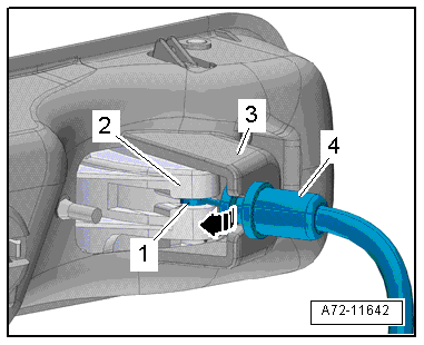
- Open coupling rod cover -1-.
- Unclip the release cable -4- at the coupling rod -2- for the release cable -arrow-.
- Remove the release cable nipple -3-.
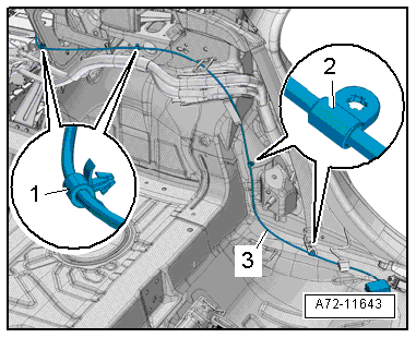
- Remove coupling rod for the release cable on the vehicle underbody.
- Unclip the brackets -1 and 2- for the release cable and remove the release cable -3- along with the coupling rod.
Installing
Install in reverse order of removal. Note the following:
Installation notes, for example tightening specifications, replacing components. Refer to → Chapter "Overview - Locking Mechanism, Avant".
Backrest Release Bracket, Removing and Installing
Removing
- Remove the luggage compartment side trim. Refer to → Chapter "Luggage Compartment Side Trim Panel, Removing and Installing, Avant".
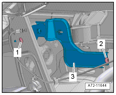
- Remove the bolts -1 and 2- for the release bracket.
- Remove the release bracket -3-.
Installing
Install in reverse order of removal. Note the following:
- Install the bolt -1- first.
- Tighten the bolt in the following sequence: -2, 1-.
Installation notes, for example tightening specifications, replacing components. Refer to → Chapter "Overview - Locking Mechanism, Avant".
Pass-Through Cover Frame, Removing and Installing
Special tools and workshop equipment required
- Pry Lever -80-200-
Removing
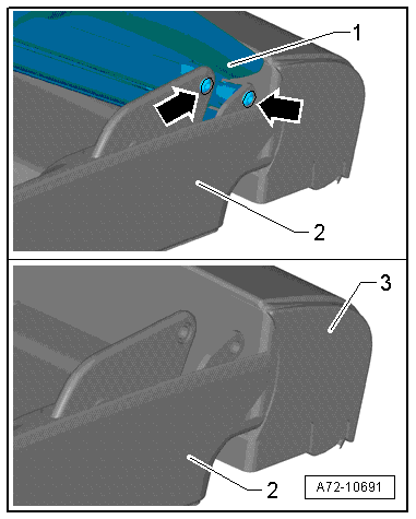
- Fold down the rear center armrest and open the pass-through door.
- Release the cover retaining tabs -1- from the rear seat backrest to do this push with the Pry Lever -80-200- on the cover frame in direction of -arrow A-.
- Pry the cover frame -2- from the rear seat backrest in direction of -arrow B-.
- Repeat the procedure for the rest of the retaining tabs -arrows-.
Installing
Install in reverse order of removal. Note the following:
- Make sure the cover frame engages completely in the rear seat backrest.
Installation notes, for example tightening specifications, replacing components. Refer to → Chapter "Overview - Center Armrest, Backrest with Pass-Through".

Pass-Through Cover, Removing and Installing
Removing
- Fold down the center armrest and open the pass-through door.
- Remove the bolts -2-.
- Remove the center armrest with the cover -1- for the pas through door.
- Fold up the rear center armrest -1-2/3.
- Remove the bolts -arrows-.
- Remove the pass-through door -2- from the center armrest.
- Remove the lower center cushion -3-. Refer to → Chapter "Lower Center Cushion, Removing and Installing".
Installing
- Install the pass-through door -1- and the center armrest and tighten the bolts hand tight.
- Close the pass-through door and align.
- Tighten the bolts -2- on the rear seat backrest.
Install in reverse order of removal.
Installation notes, for example tightening specifications, replacing components. Refer to → Chapter "Overview - Center Armrest, Backrest with Pass-Through".

