Audi A6 Typ 4G: Fuel Filler Door Unit
Overview - Fuel Filler Door Unit
Overview - Fuel Filler Door Unit
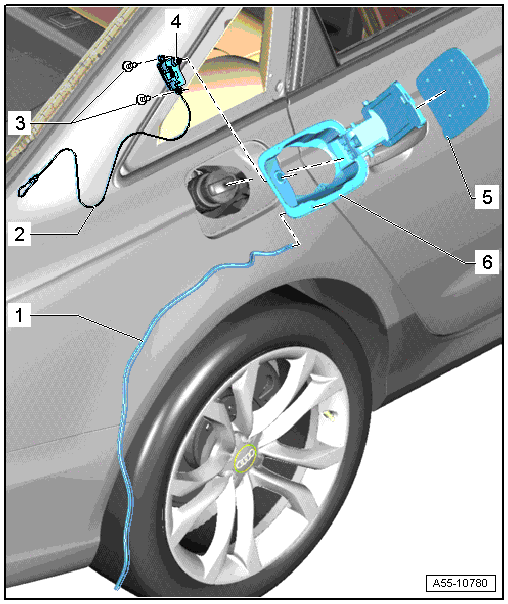
1 - Drain Hose
- Make sure it is routed correctly.
2 - Emergency Release Cable
- Routing
3 - Screws
- 1.5 Nm
4 - Fuel Filler Door Unlock Motor -V155-
- Removing. Refer to → Chapter "Fuel Filler Door Unlock Motor -V155-, Removing and Installing".
5 - Fuel Filler Door Cover
- Removing and installing. Refer to → Chapter "Fuel Filler Door Cover, Removing and Installing".
6 - Fuel Filler Door Unit
- Must be replaced after removing
- Removing and installing. Refer to → Chapter "Fuel Filler Door Unit, Removing and Installing".
Overview - Fuel Filler Door Emergency Release
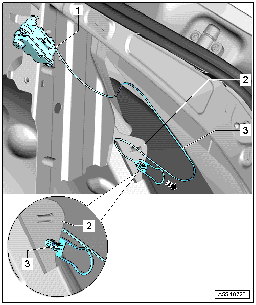
1 - Fuel Filler Door Unlock Motor -V155-
2 - Side Panel
- Mount the cable tab here.
3 - Emergency Release Cable
- Insert the Fuel Filler Door Unlock Motor -V155- with the cable over the tank opening.
- Pull the cable back into the vehicle interior and connect it with the tab on the flange on the side panel.
Overview - Fuel Filler Door Unit Drain Hose
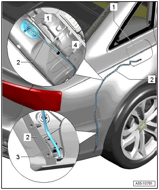
1 - Fuel Filler Door
2 - Drain Hose
- Route the drain hose as shown under the wheel housing liner and insert it in the guide piece.
3 - Rear Guide Piece
- The drain hose is attached in the lower guide inside the bumper as illustrated.
4 - Adhesive Tape
- When installing, secure the drain hose with tape as illustrated.
Fuel Filler Door Unit, Removing and Installing
Fuel Filler Door Unit, Removing and Installing
Removing
- Remove the cover from the luggage compartment right side trim panel.
- Unhook and remove the handle for the emergency release cable.
- Pull the drain hose out of the guide on the bumper. Refer to → Chapter "Overview - Fuel Filler Door Unit Drain Hose".
- Open the fuel filler door.
- Remove the fuel cap for fuel tank filler tube.
- Release the fuel filler door unit at the markings -arrows-.
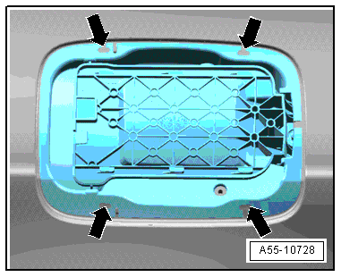
- To do this, insert a small screwdriver diagonally from underneath through the marking in the tank flap insert over the latches.
- Gently lift the screwdriver and release the latches.
- Remove the fuel filler door unit from the opening in the body, while doing this guide out the emergency release cable.
- Remove the fuel tank lid unlock motor. Refer to → Chapter "Fuel Filler Door Unlock Motor -V155-, Removing and Installing".
Installing
Install in reverse order of removal. Note the following:
 Note
Note
The fuel filler door unit must be replaced each time after removing.
- Guide the emergency release cable through the opening to the luggage compartment.
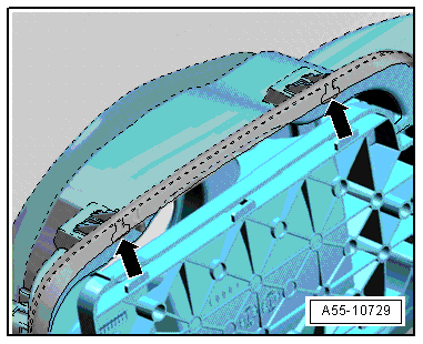
- Insert fuel filler door diagonally until catches on protruding flange engage in side panel.
Installed Position of the Fuel Filler Door Unit
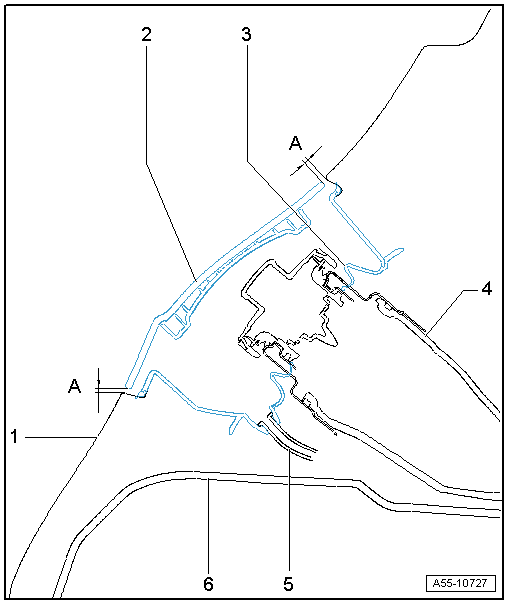
1 - Side Panel
2 - Fuel Filler Door Cover
- Adjust distance -A- = 2.2 mm evenly to the side panel.
3 - Fuel Filler Door
- Slide all around onto filler tube as shown.
4 - Filler Neck
5 - Drain Hose
- Route it without kinking it.
6 - Wheel Housing
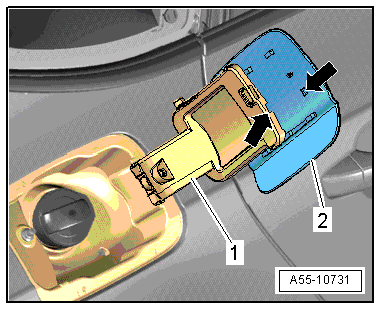
Fuel Filler Door Cover, Removing and Installing
Removing
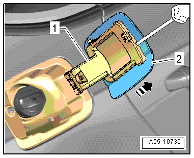
- Insert a small screwdriver between the fuel filler door -1- and the cover -1- as illustrated and unlock the catch.
- Pull the door slightly toward rear -arrow- out of the locking mechanism.
Installing
Install in reverse order of removal. Note the following:
- Install the cover into the openings in the fuel filler door.
- Slide the cover -2- forward until locking mechanism -arrows- on mount -1- engages.
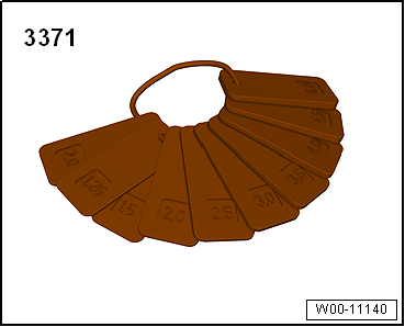
Special Tools
Gauge - Gap Adjustment -3371-