Audi A6 Typ 4G (2011–2018) Workshop Manual / Body / Body Exterior / Exterior Equipment / Overview - Wheel Covers
Audi A6 Typ 4G: Overview - Wheel Covers
Overview - Front Wheel Covers

1 - Wheel Cover
- Removing and installing. Refer to → Chapter "Fender Molding, Replacing".
2 - Fender
3 - Adhesive Tape
4 - Centering Pin
Overview - Rear Wheel Covers

1 - Side Panel Fender Molding
- Removing and installing. Refer to → Chapter "Wheel Cover for Side Panel and Rear Door, Replacing".
2 - Rear Door Trim
- Removing and installing. Refer to → Chapter "Wheel Cover for Side Panel and Rear Door, Replacing".
3 - Side Panel
4 - Adhesive Tape
Overview - Heat Shield
Overview - Front Heat Shield
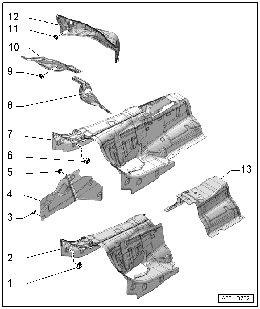
1 - Nut
- Quantity: 4
- 2.1 Nm
2 - Front Heat Shield
- For the center of the tunnel
- For vehicles with a TDI engine
- Removing and installing. Refer to → Chapter "Heat Shield for Front Center Tunnel, Removing and Installing, Vehicles with TDI Engine".
3 - Spring Clip
- Quantity: 3
4 - Heat Shield
- For the longitudinal member
- Removing and installing on vehicles with a gasoline engine: left refer to → Chapter "Left Longitudinal Member Heat Shield, Removing and Installing, Vehicles with Gasoline Engine", right refer to → Chapter "Right Longitudinal Member Heat Shield, Removing and Installing, Vehicles with Gasoline Engine"
- Removing and installing on vehicles with a TDI engine: left refer to → Chapter "Left Longitudinal Member Heat Shield, Removing and Installing, Vehicles with TDI Engine", right refer to → Chapter "Right Longitudinal Member Heat Shield, Removing and Installing, Vehicles with TDI Engine"
5 - Lock Washer
6 - Nut
- Quantity: 4
- 2.1 Nm
7 - Heat Shield
- For the center of the tunnel
- For vehicles with a gasoline engine
- Removing and installing. Refer to → Chapter "Heat Shield for Center Tunnel, Removing and Installing, Vehicles with Gasoline Engine".
8 - Left Heat Shield
- For the top of the tunnel
- There are different versions. Refer to the Parts Catalog.
- Removing and installing. Refer to → Chapter "Heat Shield for Left Upper Tunnel, Removing and Installing".
9 - Lock Washer
- Left: 2 washers, right: 3 washers
10 - Right Heat Shield
- For the top of the tunnel
- There are different versions. Refer to the Parts Catalog.
- Removing and installing. Refer to → Chapter "Heat Shield for Right Upper Tunnel, Removing and Installing".
11 - Lock Washer
- Quantity: 2
12 - Heat Shield
- For the plenum chamber bulkhead
- Audi RS 6 vehicles with additional vacuum line covering
- Removing and installing in vehicles with a gasoline engine. Refer to → Chapter "Heat Shield, Removing and Installing, Plenum Chamber Bulkhead, Vehicles with Gasoline Engine".
- Removing and installing in vehicles with a TDI engine. Refer to → Chapter "Heat Shield, Removing and Installing, Plenum Chamber Bulkhead, Vehicles with TDI Engine".
13 - Rear Heat Shield
- For the center of the tunnel
- For vehicles with a TDI engine
- Removing and installing. Refer to → Chapter "Heat Shield for Rear Center Tunnel, Removing and Installing, Vehicles with TDI Engine".
Overview - Rear Heat Shield
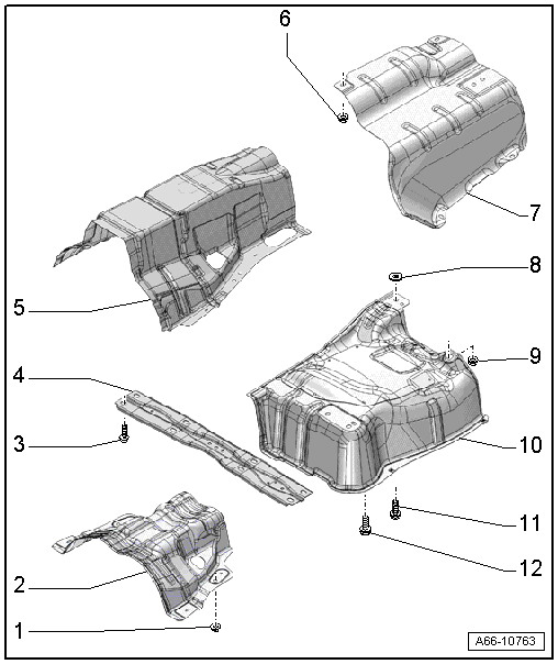
1 - Nut
- 2.1 Nm
- Quantity: 2
2 - Heat Shield
- For the propshaft
- Removing and installing. Refer to → Chapter "Propshaft Heat Shield, Removing and Installing".
3 - Bolt
- 55 Nm
- Quantity: 8
4 - Crossbrace
- Removing and installing. Refer to → Chapter "Tunnel Bridge, Removing and Installing".
5 - Heat Shield
- For the back of the tunnel
- Removing and installing. Refer to → Chapter "Heat Shield for Rear Tunnel, Removing and Installing".
6 - Nut
- Quantity: 4
- 2.1 Nm
7 - Heat Shield
- For the rear muffler
- Removing and installing. Refer to → Chapter "Rear Muffler Heat Shield, Removing and Installing".
8 - Washer
9 - Nut
- 2.1 Nm
10 - Heat Shield
- For the center of the exhaust system
- Removing and installing. Refer to → Chapter "Center Exhaust System Heat Shield, Removing and Installing".
11 - Bolt
- Tightening specification. Refer to → Fuel Supply System; Rep. Gr.20; Fuel Tank; Overview - Fuel Tank.
12 - Bolt
- 20 Nm
- Vehicles with center muffler: Tightening specification. Refer to → Engine Mechanical, Fuel Injection and Ignition; Rep. Gr.26; Exhaust Pipes/Mufflers; Overview - Muffler

